Do you have a question about the Gree Vireo B 9 MBH and is the answer not in the manual?
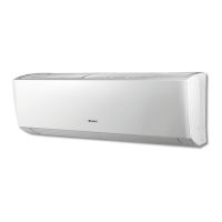
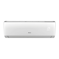
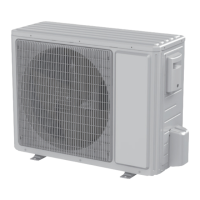
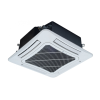
Provides a brief overview of the product and its components.
Details technical specifications for cooling, heating, and electrical parameters.
Illustrates the physical dimensions of the indoor and outdoor units.
Shows the flow of refrigerant within the system.
Covers wiring diagrams and PCB layouts for electrical connections.
Explains the operational modes and control functions of the unit.
Displays graphs showing current vs. compressor frequency for cooling and heating.
Shows how cooling and heating capacity changes with outdoor temperature.
Provides detailed performance data under rated conditions.
Presents noise levels for indoor and outdoor units at different operating speeds.
Details electrical wiring connections for indoor and outdoor units.
Shows the layout of components on the indoor unit's printed circuit board.
Illustrates the component layout for the outdoor unit's printed circuit board.
Explains the buttons and icons of the remote controller.
Details the functions of individual buttons on the remote controller.
Describes functions activated by pressing multiple buttons simultaneously.
Provides detailed explanations of various operating modes and functions.
Details specific operational modes and protection functions.
General information and specifications for outdoor units.
Covers compensation and calibration of input parameters for outdoor units.
Describes specific functions like defrosting and refrigerant recovery for outdoor units.
Explains the operational logic for compressor, fans, and 4-way valve.
Details various protection mechanisms to prevent damage and ensure safety.
Continues detailing protection functions like frequency limiting and voltage sag.
Outlines procedures for various protection functions and fault detections.
Provides procedures for handling sensor protection faults and failures.
Provides important safety precautions and guidelines before installation and maintenance.
Lists main tools required and details electrical and installation safety precautions.
General guidance and steps for installing the air conditioning unit.
Shows recommended clearances and dimensions for unit placement.
Provides a visual flowchart of the installation steps.
Lists parts to be checked before installation.
Guides on choosing optimal locations for indoor and outdoor units.
Details electrical connection requirements and safety.
Provides step-by-step instructions for installing the indoor unit.
Instructions for connecting the refrigerant pipes to the indoor unit.
Details how to connect and route the drain hose.
Instructions for connecting the electrical wires to the indoor unit.
Steps for mounting the indoor unit onto the wall frame.
Provides comprehensive instructions for installing the outdoor unit.
Explains the process of vacuum pumping and checking for refrigerant leaks.
Lists checks and steps for test operation after installation.
General information on maintenance tasks.
Lists error codes displayed by the unit and their corresponding malfunctions.
Provides guidance on diagnosing and resolving common malfunctions.
Troubleshooting steps for indoor fan motor blocked protection (H6).
Troubleshooting steps for jumper cap protection issues.
Troubleshooting steps for communication malfunctions between units (E6).
Diagnoses and resolves capacitor charge faults in the outdoor unit.
Diagnoses high temperature and overload protection issues.
Addresses common malfunctions and their troubleshooting steps.
Troubleshooting for ODU fan motor, compressor, and refrigerant leaks.
Addresses troubleshooting for unusual sounds and vibrations.
Provides an overview of exploded views and parts lists.
Provides an exploded view diagram of the indoor unit components.
Lists the part codes and quantities for the indoor unit assembly.
Shows an exploded view diagram of the outdoor unit components.
Lists the part codes and quantities for the outdoor unit assembly.
General instructions for component removal.
Step-by-step guide for disassembling the indoor unit.
Continues the process of removing parts from the indoor unit.
Step-by-step guide for disassembling the outdoor unit.
Details the correct method for expanding refrigerant pipes to prevent leaks.
Provides temperature conversion tables between Celsius and Fahrenheit.
Specifies connection pipe lengths, height differences, and refrigerant charging.
Lists resistance values for temperature sensors at different temperatures.
Provides contact details for GREE Electric Appliances, Inc.
| Brand | Gree |
|---|---|
| Model | Vireo B 9 MBH |
| Category | Air Conditioner |
| Language | English |