Retaining Angle
Thermal Blanket
(installed around
entire outside
surface of sleeve)
2 in. Max.
6 in. Max.
6 in. Max.
2 in. Max.
Wall
Figure 4: Sleeved damper with Thermal
Blanket (duct continuation).
Note: Thermal blanket is riveted to the damper sleeve and
the seam is taped with acrylic adhesive tape, FSK facing
tape 152 5CWnt, manufactured by Venture Tape Company.
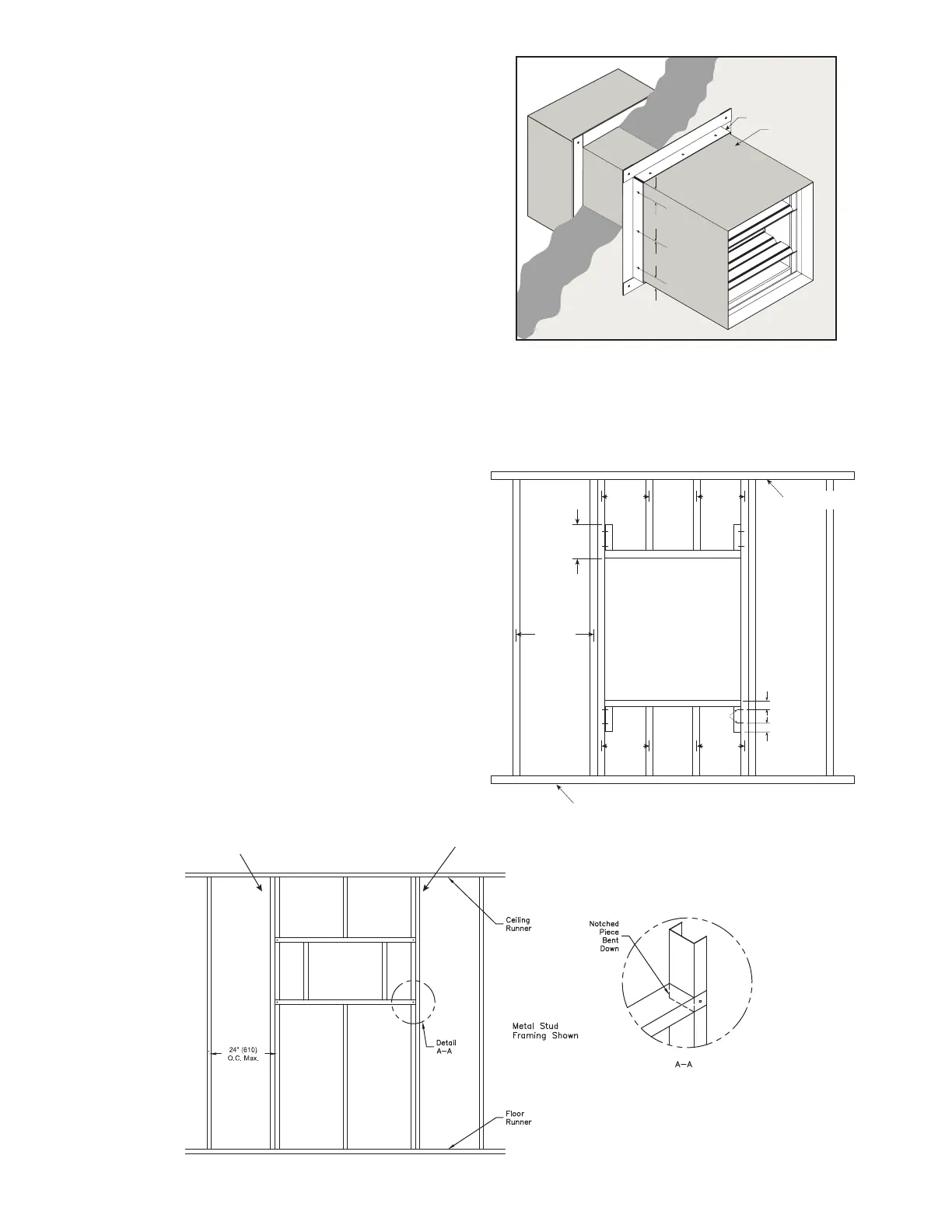
12 in.
24 in. o.c.
Maximum
Floor Runner
Ceiling Runner
24 in. o.c.
Maximum
(metal studs)
24 in. o.c.
Maximum
(metal studs)
16 in. o.c.
Maximum
(wood studs)
16 in. o.c.
Maximum
(wood studs)
2 in. (51mm)
2 in. (51mm)
2 Panhead
Screws
Figure 5
5. ACTUATOR CONNECTIONS
Electrical and/or pneumatic connections to damper
actuators should be made in accordance with wiring
and piping diagrams developed in compliance with
applicable codes, ordinances and regulations (see
Electrical Guidelines).
6 Recommended Preparation of Openings in
Wood and Metal Stud Walls
• Frame wall openings as shown (see Figure 5 & 5A)
• Gypsum wall board must be fastened 12 in. (305mm)
on center to all stud and runner flanges surrounding
opening (see Figure 5 & 5A).
• Prepare opening between studs and sleeve assembly
as shown (Figure 6 & 7).
• All construction and fasteners must meet the
requirements of the appropriate wall design (See UL
Fire Resistance Directory) and/or local codes.
4. SECURING THE DAMPER/SLEEVE ASSEMBLY TO
WALL OPENINGS continued....
• Retaining angles must be attached to the sleeve using
one or more of the following methods of attachment:
• Tack or spot welds
• #10 (19mm) sheet metal screws
•
1
⁄4 in. (6mm) bolts and nuts
•
3
⁄16 in. (4.7mm) steel pop rivets
Attachments must be spaced a maximum of 6 in.
(152mm) on center and a maximum of 2 in. (51mm) from
corners. The angles must be attached to all 4 sides of
the sleeve. A minimum of two attachments are required
on each side, top and bottom. The angles need not be
attached to each other at the corners.
Caution! Do not tear the thermal blanket during
installation.
Dampers are tested for correct operation and are
square and straight before shipment from the factory.
Dampers must be installed square and straight and
must not be twisted or racked. Failure to install the
damper square and straight may prevent the damper
blades from operating open and closed.
Second set of studs are not required on openings
36 in. x 36 in. (914mm x 914mm) or smaller.
Metal stud only
Figure 5A
 Loading...


