Breakaway Connections
Proprietary Flange System Breakaway Connections
(TDC by Lockformer, TDF by Engle)
TDC and TDF systems are
approved as breakaway
connections when installed as
described in the TDC or TDF
addendum to the SMACNA Duct
Construction Standards except
the corners may not be bolted.
Standard 6 in. (152mm) metal
clip may be used with spacing as shown in Figure 9. 3/8
in. (9.5mm) metal bolts and nuts may be used to fasten
together corner pieces (see Figure 10).
Duct
Sleeve
6 in.
Std. Clip
Length
C
L
Duct
60 in. Duct
4 Req’d.
48 in. Duct
3 Req’d.
36 in. Duct
3 Req’d.
24 in. Duct
2 Req’d.
18 in. Duct &
Smaller
1 Req’d.
Clip Spacing
Typical TDC/TDF joint
6 in. 6 in.
9 in.
7 in.7 in.
5 in. 5 in.
5 in.5 in.
Traditional Breakaway Style Transverse Joints
Transverse joints illustrated at right have always been
approved as breakaway connections. SMACNA testing
has also approved the following variations as breakaway
connections.
• The breakaway connections shown (Figure 7) can be
applied with maximum of two #10 (19mm) sheet metal
screws on each side and on the bottom located in the
center of the slip pocket and penetrating both sides of
the slip pocket.
• Transverse joints illustrated can be applied as top
and bottom joints with
Drive Slip - side joints in
duct heights up to 20 inches
(508mm), See Figure 6.
Figure 6
Plain “S” Slip Hemmed “S” Slip Double “S” Slip
Inside Slip Joint Standing “S” Standing “S” (Alt.)
Standing “S” (Alt.) Standing “S” Standing “S”
(Bar Reinforced) (Angle Reinforced)
Figure 7
Round and Oval Duct Breakaway Connections
Round or flat oval ducts connected to Type R or O damper
collars shall be attached with #10 (19mm) sheet metal
screws as follows:
• Ducts to 22 in. (558mm) wide (or dia.) and smaller shall
have three screws.
• Ducts larger than 22 in. (558mm) wide (or dia.) up to
and including 36 in. (914mm) wide (or dia.) shall have
five screws.
Fire Damper Sleeve
Neoprene or Butyl gasket
between all angles
Flanged system angles
(Attach per
manufacturer's
instructions)
Duct
3/8 in. bolts in
corners are optional
6 in. long 1/16 in. max.
thickness plastic cleats;
12 in. c-c (min. 1 per side)
Figure 8
NOTE: All breakaway connections described may have duct
sealant applied, PA2084T duct sealant adhesive
manufactured by Precision, DP1010 water base duct
sealant manufactured by Design Polymetrics, Grey
Pookie, Ductmate PROseal
®
, or CL Ward S Seal in
accordance with SMACNA recommendations.
Manufactured Flanged System Breakaway
Connections
Flanged connection systems manufactured by Ductmate,
DuroDyne, Ward, and Nexus are approved as breakaway
connections when installed as illustrated (Figure 8).
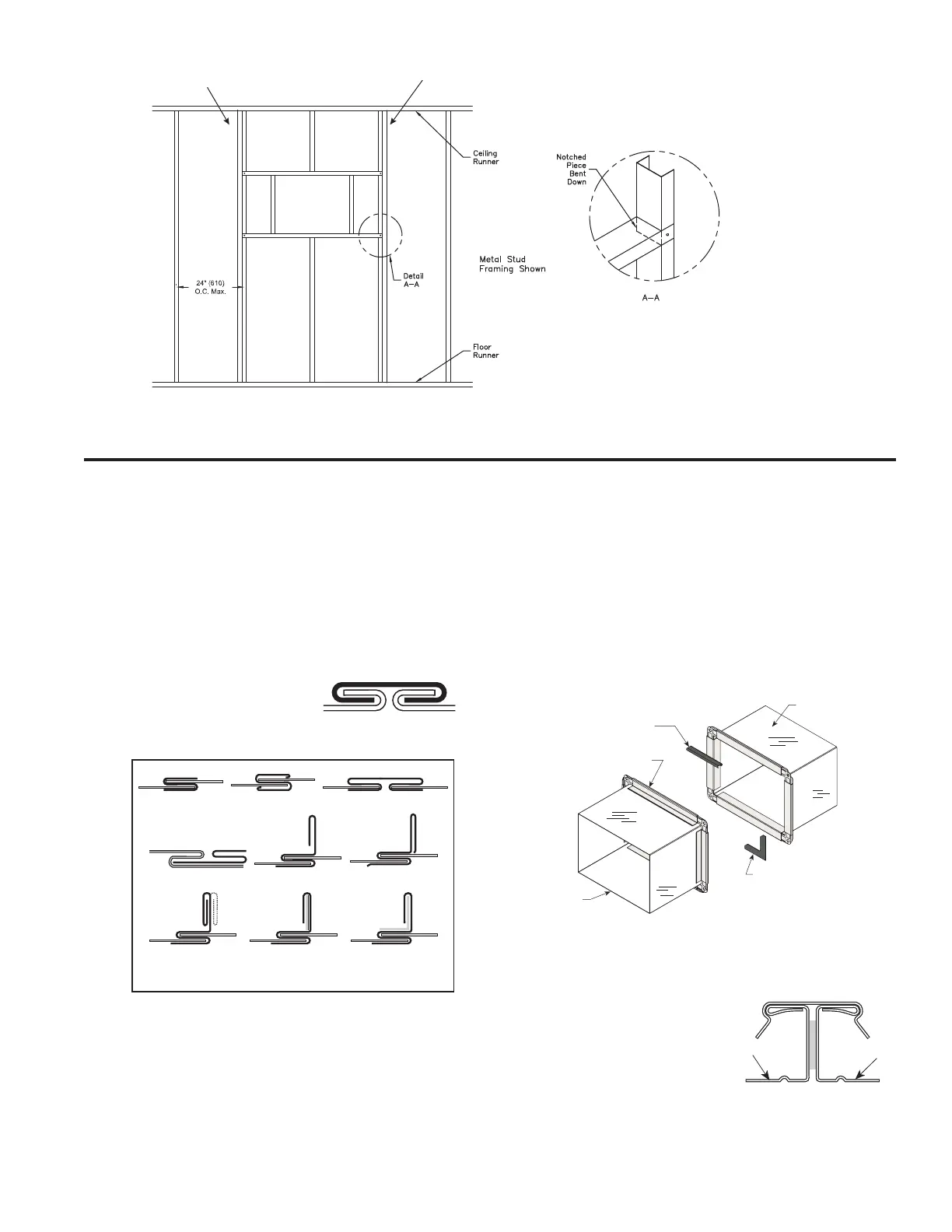
Second set of studs are not required on openings
36 in. x 36 in. (914mm x 914mm) or smaller.
Figure 4A
 Loading...


