47
Reference
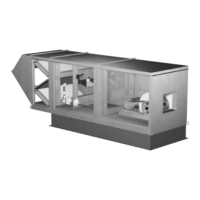
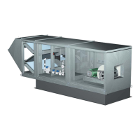
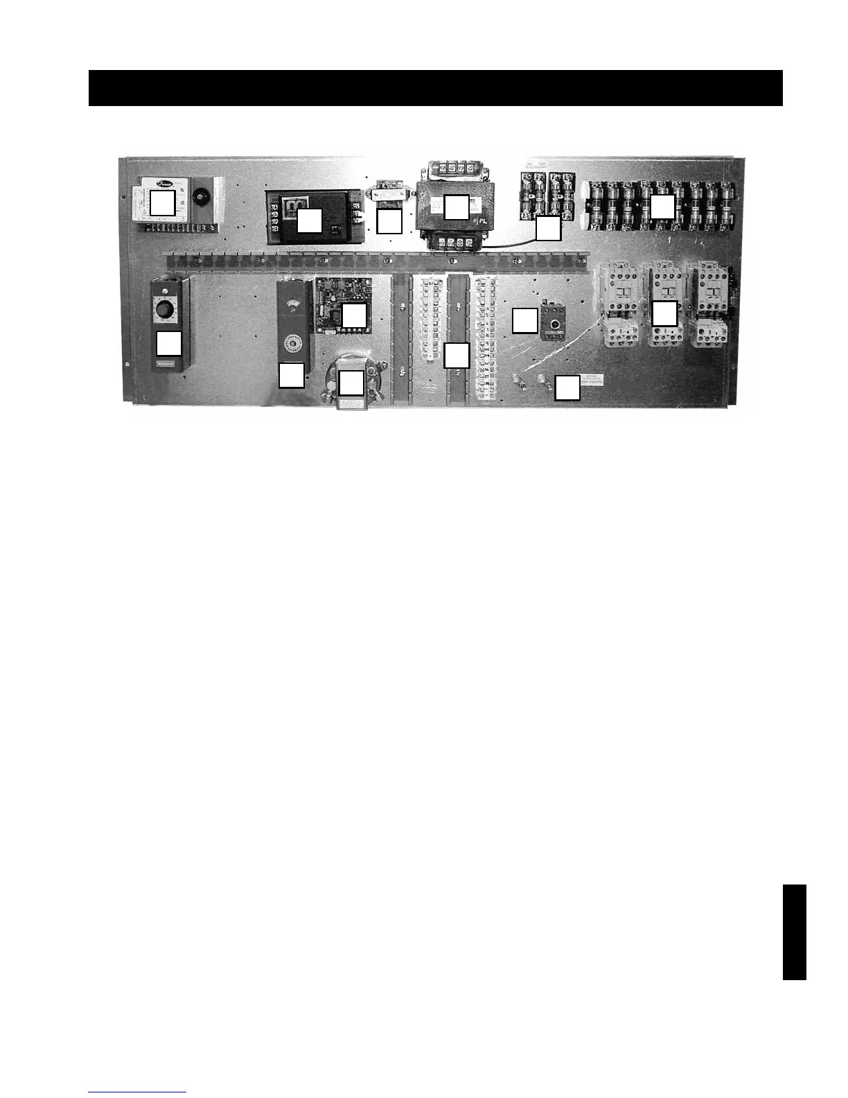
Control Center Layout
Reference
1. Heating/Cooling Inlet Air Sensor (Optional) - Ductstat that automatically de-energizes burner when inlet air
temperature rises above set point, or shuts down cooling when temperature falls below set point.
2. Flame Safeguard/Spark Generator - Monitors flame, shuts down unit when unsafe conditions are detected.
3. High Limit - Prevents unit from discharging air above a set point.
4. Building Freeze Protection (Optional) - Prevents unit from discharging air below a set point after a time
delay. Temperature and time delay are field adjustable.
5. Filter Gauge (Optional) - Monitors filter pressure drop, turns on indicating light when pressure drop is
above field adjustable set point.
6. Terminal Strip - 24 Volt power strip for control wiring.
7. Main Disconnect - On/Off switch, provides single point power connection to unit.
8. Grounding Lugs - Completes electrical circuit
9. Motor Starters - 24 Volt magnetic contacts for starting motors, comes standard with electronic overload,
may be provided with auxiliary contacts.
10. Amplifier - Controls modulating valve, assures the desired temperature is delivered.
11. Low Voltage Transformer - Reduces voltage to the Maxitrol system.
12. Control Transformer - Provides 24 Volts for controls and 120 Volts for valves.
13. Secondary fuses - Provides proper fusing for all electrical components other than the motors.
14. Motor Fuses - Provides proper fusing for supply and exhaust fan motor(s).
Figure 67. Direct Spark Gas Control Center
1
2
10
3
4
6
11
13
14
9
7
8
12
5
 Loading...