Do you have a question about the Greenheck DG and is the answer not in the manual?
Guidelines for storing units indoors, emphasizing controlled environment and protection from elements.
Procedures for storing units outdoors, focusing on level surfaces, elevation, and air circulation.
Monthly checks, lubrication, and visual inspection for units in storage to prevent deterioration.
Steps to inspect and prepare units for installation after storage, ensuring all parts are secure.
Instructions for installing ceiling hangers and supports for the indoor unit, ensuring proper load bearing.
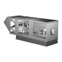
Steps for assembling and mounting the indoor unit, including attaching sections and securing to supports.
Applying sealant around the weatherhood to prevent water and drafts entering the building.
Positioning and securing roof curbs and equipment supports, ensuring they are level.
Guidelines for connecting ductwork to the unit, following industry standards for good practice.
Applying sealant to the curb and duct adapter to prevent vibration and water ingress.
Lifting and centering the unit on supports, then securing it with self-tapping screws.
Assembling and attaching the weatherhood to the unit, with specific notes for optional modules.
Sealing the seam between the weatherhood and the unit to ensure weather tightness.
Positioning and leveling roof curbs and equipment supports, including flashing.
Installing the combination curb adaptor and extension for exhaust and supply connections.
Connecting ductwork according to SMACNA, AMCA, NFPA 96, and local codes.
Applying sealant to the curb and duct adapter for vibration isolation and water prevention.
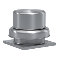
Fastening the exhaust fan to the curb extension using self-tapping screws.
Installing optional exhaust accessories like hinge kits and grease traps.
Positioning and securing roof equipment supports for the evaporative cooling module.
Applying sealant around the airstream opening to ensure an airtight seal for the module.
Lifting and centering the evaporative cooling module onto the equipment supports, aligning flanges.
Fastening the cooling module to the base unit, requiring media removal for side access.
Sizing main power lines based on unit nameplate voltage and MCA for safe operation.
Creating field-supplied openings for electrical connections, varying by unit size.
Connecting main power lines to the disconnect switch and grounding lug, torquing connections.
Wiring a separate 115V circuit for the convenience outlet, including short circuit protection.
Connecting optional accessories like stats, switches, and indicators using the ladder diagram.
Connecting the evaporative cooler pump and auto-drain/flush features per the ladder diagram.
Checking the unit's nameplate for gas type, pressure, and BTU requirements.
Installing an external regulator if supply gas pressure exceeds unit specifications.
Installing shut-off valve, test port, and drip leg for the gas supply line, ensuring accessibility.
Routing the optional vent line to the outdoors, adhering to fuel gas code requirements.
Testing supply lines and factory piping for leaks using a soap and water solution.
Connecting the water supply line, including a manual shut-off valve and solenoid.
Connecting an unobstructed drain line to the sump drain and overflow, including a trap.
Verifying and adjusting the sump tank water level for proper pump operation.
Installing the normally closed supply line solenoid upstream of the manual supply valve.
Installing the normally open drain line solenoid between the manual supply valve and the supply solenoid.
Wiring the supply and drain solenoids according to the unit's wiring diagram.
Wiring the temperature sensor to the control center terminals if the cooler shipped separately.
Accessing the distributor by removing the access panel and verifying nozzle placement.
Connecting the suction line from the compressor to the unit's suction connection.
Installing the liquid line and TEV, following manufacturer recommendations for valve installation.
Securing the expansion valve's remote sensing bulb to the suction line and insulating it.
Pressurizing coil piping with nitrogen and checking for leaks to ensure integrity.
Evacuating the coil and piping to 500 microns or less to remove moisture and ensure proper function.
Connecting an unobstructed drain line to the drain pan, including a trap.
Checking the coil's hand designation for correct plumbing for counter-flow heat exchange.
Pressurizing the coil with nitrogen and checking for leaks for a minimum of 10 minutes.
Connecting the supply and return piping to the chilled water coil.
Mounting the pressure tap to the unit exterior in a location free from prevailing winds.
Connecting pressure tap lines from the unit to the photohelic gauge and the space.
Adjusting the photohelic gauge knobs to set the desired building pressure limits.
Steps to install and adjust the dirty filter switch for indicating dirty filters.
Verifying belt alignment, tension, fastener tightness, and free rotation before running the blower.
Checking blower voltage, rotation, vibration, motor condition, and air volume measurements.
Adjusting settings for optional components like inlet air sensors and freeze protection.
Verifying and adjusting supply gas pressure to meet unit nameplate requirements.
Verifying high (8 in. wg) and low (3 in. wg) gas pressure switch settings.
Measuring static pressure across the burner with a manometer and adjusting baffles for proper airflow.
Setting the low fire time delay to 75% of maximum, ensuring at least 10 seconds of low fire.
Adjusting the regulator to achieve the designed temperature rise by monitoring inlet/discharge temperatures.
Adjusting the modulating valve needle to achieve a continuous flame ribbon across the burner.
Setting the operating temperature based on the Maxitrol controller model (Series 14, 44, or SC25S).
Measuring the flame signal using a multimeter to ensure proper burner ignition feedback.
Verifying media orientation, stainless steel caps, and distribution headers are correctly installed.
Ensuring the pump filter is present and clean at the pump inlet.
Filling the sump tank and adjusting the float valve to achieve the correct water level.
Saturating the media with water for 20 minutes with the blower off to condition it.
Verifying pumps saturate media in 45-60 seconds and adjusting manual ball valve if needed.
Adjusting the bleed-off rate based on water mineral content and service intervals.
Configuring the auto drain/fill timer for daily flushing and freeze protection based on outside air.
Removing the jumper and energizing the blower to put the evaporative cooler into operation.
Activating Flow Test Mode by pressing Function key to open the supply solenoid.
Adjusting the manual supply valve to achieve the recommended water pressure for media saturation.
Leaving the supply solenoid open for 20 minutes to saturate and break in the media.
Deactivating Flow Test Mode to close the supply solenoid after pressure is set.
Checking media condition after one hour of operation for dryness or excessive drainage.
Accessing Program Mode by pressing and holding the Enter key for three seconds.
Navigating to the "toF" setting and adjusting the minimum cooling temperature as needed.
Exiting Program Mode after settings are saved or after a period of inactivity.
Navigating to the "Frt" setting and adjusting the freeze temperature to prevent damage.
Exiting Program Mode after settings are saved or after a period of inactivity.
Using variable volume to track exhaust and provide required make-up air, controlling via VFDs or modulating blowers.
Testing 2-speed VFD motor operation by switching speeds via remote control panel.
Testing potentiometer control by adjusting to extremes to confirm full range of fan speed operation.
Testing building pressure control by setting pressure limits and observing VAV system response.
Verifying VFD response to external 2-10 VDC or 4-20 mA signals for blower speed control.
Testing variable kitchen control for automatic adjustment of make-up air based on cooking loads.
Understanding the function of the self-adjusting burner bypass damper for maintaining combustion airflow.
Testing the 2-position damper by toggling the recirculating switch and observing damper movement.
Testing modulating damper control by turning the potentiometer to confirm full open/closed return air damper operation.
Testing building pressure control by setting pressure limits and observing return air damper response.
Verifying return air damper response to external 2-10 VDC or 4-20 mA signals.
Outlines the sequence of electrical contacts and components for fan and heat activation.
Describes the step-by-step burner ignition sequence from supply fan start to flame monitoring.
Diagnostic flowchart to identify and resolve issues when the blower fails to start.
Diagnostic flowchart to identify causes of motor overcurrent, such as high air volume or incorrect voltage.
Diagnostic flowchart to identify causes of low airflow, including damper issues, static losses, or belt slippage.
Diagnostic flowchart to identify causes of excessive airflow, such as high blower speed or insufficient static pressure.
Diagnostic flowchart to identify causes of noise and vibration, like worn belts, misaligned sheaves, or unbalanced wheels.
Diagnostic flowchart for issues preventing the heater from attempting to light, checking voltage, switches, and safeties.
Diagnostic flowchart for issues when the heater attempts to light but fails to produce a flame, checking gas pressure and spark.
Diagnostic flowchart for evaporative cooler pump operation issues, checking voltage, sensors, and relays.
Troubleshooting steps for water carryover from the evaporative cooler, checking headers and air velocity.
Diagnosing and correcting issues with low or high water supply to the Water Wizard™™ system.
Checking V-belt wear, tension, alignment, and replacing belts and sheaves as needed.
Cleaning and oiling fan wheels when dust or oil accumulation causes imbalance.
Following the lubrication schedule and guidelines for fan bearings to ensure longevity.
Cleaning exterior surfaces and lubricating motors with grease fittings as recommended.
Cleaning aluminum mesh filters or replacing disposable filters based on inspection.
Testing fluid, maintaining velocities, and venting coils periodically to ensure proper operation.
Brushing and flushing media to reduce mineral build-up and ensuring correct reinstallation.
Inspecting coils for corrosion/leaks, cleaning surfaces, and maintaining the drain pan.
Repeating blower and direct gas start-up steps to ensure proper settings for the heating season.
Checking and resetting the high limit switch, which may have tripped during summer.
Inspecting burner for scale, clearing ports, and checking fasteners and flame/spark rods.
Checking gas connections, joints, and valves annually for tightness and leaks.
Shutting off water and draining lines when temperatures drop below 45°F to prevent freezing.
Protecting chilled water coils from freezing by blowing out or flushing with inhibited glycol.
Illustrates a typical direct spark ignition gas train configuration with key components.
Diagram and list of components within the unit's control center for easy identification and access.
Checklist for verifying direct gas supply pressure, switches, and firing rates.
Checklist for verifying wiring, blower rotation, voltage, gas pressure, and remote controls.
Checklist for verifying blower voltage, rotation, vibration, motor amps, and CFM.
Checklist for setting up optional accessories like inlet air sensors and building freeze protection.
Checklist for verifying evaporative cooler media orientation, water flow, and header alignment.
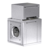
| Wheel Type | Backward inclined |
|---|---|
| Drive Type | Direct |
| Static Pressure Range | Up to 6 in. wg |
| Construction | Heavy-duty steel |
| Motor Type | TEFC |
| Mounting | Wall |