Do you have a question about the Greenheck FGI and is the answer not in the manual?
Procedures for receiving, inspecting, unpacking, and handling the ventilator unit to prevent damage.
Essential safety guidelines for qualified personnel to ensure safe installation and operation.
Steps for assembling the base frame, including ends, sides, and support angles.
Installation of hood rails, birdscreens, and hood panels to complete the standard assembly.
Steps for assembling the base and installing birdscreens for high wind rated hoods.
Assembly of hood rail, hat channel, and hood panels for high wind conditions.
Guidelines for installing the hood and securing it to the roof curb.
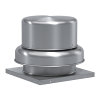
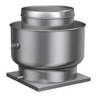
The document describes the installation, operation, and maintenance of the Greenheck Fabra Hood Gravity Ventilator, specifically models FGI and FGR with a birdscreen. This ventilator is designed for single-section applications where the throat length is 72 inches or less.
The Fabra Hood Gravity Ventilator serves as either an intake (Model FGI) or relief (Model FGR) system, suitable for natural gravity or negative pressure ventilation setups. Its primary function is to facilitate air movement into or out of a building, contributing to overall air quality and temperature regulation. The design incorporates a low-silhouette, fabra hood-style housing, which offers several advantages. This housing is engineered for superior load-bearing strength, ensuring structural integrity and durability in various environmental conditions. It also provides excellent weather resistance, protecting internal components from the elements and maintaining operational efficiency. Furthermore, the design offers dimensional flexibility, allowing for adaptation to different installation requirements, and a pleasing aesthetic appearance that can integrate well with building architecture. The inclusion of a birdscreen is a key feature, preventing birds and other large debris from entering the ventilation system, thereby protecting the fan and maintaining airflow integrity.
The installation process for the Fabra Hood Gravity Ventilator is detailed, with specific instructions for both standard and high-wind assembly configurations. For standard assembly, the process begins with opening crates and separating parts, followed by placing and fastening the base ends and sides. Fasteners should initially be hand-tightened and fully secured only after several steps, ensuring proper alignment and fit. Reinforcing plates are required in the corners of the base for units where the difference between hood width and throat width exceeds 32 inches, enhancing structural stability. The hood support angles are then attached to the base assembly, with some units featuring pre-attached diagonal braces that also need to be fastened to the base. After these initial structural components are in place, all fasteners are tightened, and all inside corners where base sections meet are caulked to ensure a watertight seal. At this point, the base assembly can be lifted onto the roof curb, ready for the next stages of assembly.
The side birdscreen assembly is attached to the hood support angle and base assembly using specific fasteners. Subsequently, the end birdscreen assembly is installed, with birdscreen clips needing to be turned to secure them under both the side birdscreen frame extension and the hood support angle. These clips may need to be loosened and tightened as necessary for proper fit. The hood rail assembly is then attached to the hood support angles using bolts and Nyloc nuts, with fasteners again being hand-tightened until a later step. The hood panels are assembled to the hood rail assembly, starting with the "male rib" end assembly, followed by interlocking panels. Each hood panel is secured with sheet metal screws and sealing washers. For hoods over 9 feet wide, special hood clips are supplied and installed as panels are put in place, requiring access to the underside of the hood, which means the end birdscreen assembly might need to be left out until the hood is fully assembled. The "female rib" end assembly is installed last. Finally, all pivot bracket fasteners are tightened.
For high-wind assembly, the instructions are largely similar but emphasize the potential ease of assembling the unit on the ground and then lifting it to the roof, especially for larger hoods. A critical warning is issued: do not climb on top of the hood to fasten screws in the center. The high-wind assembly also includes specific hardware kits for thread cutters and whiz nuts, used to install the hood rail assembly and hat channel. The hat channel supports the hood panels and is fastened to diagonal end panel supports. Adjustment of the hat channel may be necessary to ensure a minimal gap between it and the hood panel. Thread rolling screws are used to attach the hood end panel to the diagonal end panel supports, and self-tapping screws secure the hood panel to the hat channel and hood rail assembly. Special attention is given to securing male and female rib joints with sheet metal screws, with an important note not to drive screws all the way through both sides of the ribs to prevent water leakage. The final steps involve lifting the completed hood assembly onto the hood base and tightening all pivot bracket fasteners.
The manual also provides detailed anchoring options for different deck types: timber, steel, and concrete. For timber decks, options include lag screws or thru-bolts, with specifications for minimum penetration, thread engagement, and edge distance. Steel decks offer self-drilling screws or thru-bolts, with requirements for thread embedment and edge distance. Concrete decks utilize screw anchors or thru-bolts, specifying minimum embedment and concrete thickness. These anchoring details are crucial for ensuring the ventilator's stability and resistance to high winds, with quantities varying by fan size and specific footnotes for installation notes.
The document highlights the importance of proper handling during receiving and unpacking to prevent damage. Upon receiving the product, it is crucial to check all items against the delivery receipt or packing list and inspect for any shipping damage. Any detected damage should be reported to the carrier and noted on the delivery receipt, countersigned by the carrier. Physical damage after acceptance is not the manufacturer's responsibility, emphasizing the need for thorough inspection upon arrival.
When unpacking, all required parts and quantities should be verified. Missing items should be reported to the local representative for replacement. The manual notes that due to transportation and truck space availability, not all items for the unit may be shipped together, and confirmation of shipments should be limited to items on the bill of lading.
For handling, the manual advises careful lifting to avoid damaging the housing. Fans should be rigged and moved using optional lifting brackets or by the skid with a forklift. Handling should be done in a manner that prevents scratching or chipping of the coating, as a damaged finish can reduce the ventilator's ability to resist corrosion.
The general safety information emphasizes that only qualified personnel should install the fan, possessing a clear understanding of the instructions and general safety precautions. Improper installation can lead to electric shock, injury from moving parts, and other hazards. Additional considerations for high winds or seismic activity may require consultation with a licensed professional engineer.
The document implicitly suggests that proper installation, including tightening all fasteners and caulking inside corners, contributes to the long-term maintenance and performance of the ventilator by ensuring structural integrity and weather resistance. The detailed instructions for different assembly types and anchoring options are designed to ensure the ventilator is installed correctly, minimizing future maintenance issues related to structural failure or weather damage.
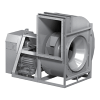
| Application | General ventilation, exhaust, supply air |
|---|---|
| Wheel Type | Backward Inclined |
| Drive Type | Direct Drive |
| Housing Material | Galvanized Steel |
| Construction | Heavy-duty |
| Temperature Range | -40°F |