Direct Spark Ignition Make-Up Air 37
®
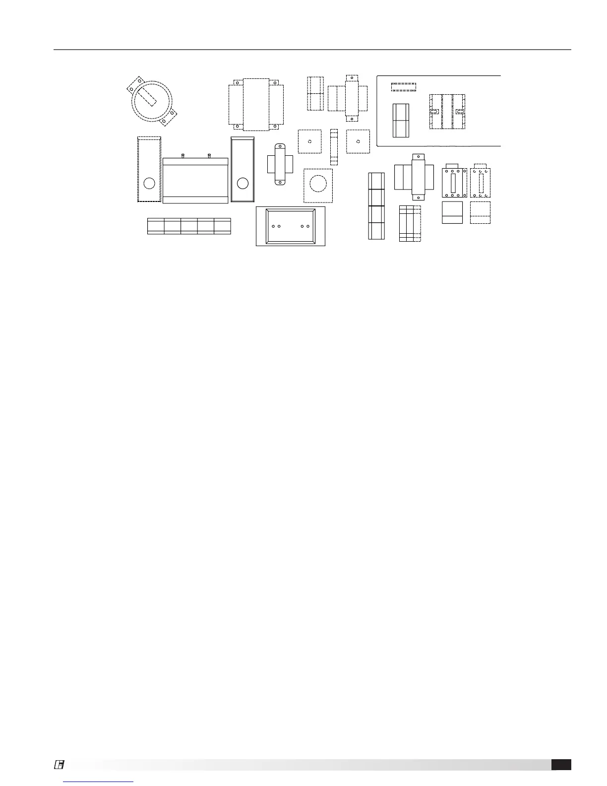
Control Center Layout
Reference
13 22
26 28
27
20
15
21
4
1 78
29
3
5
16
23
17
18
1914
25
10
12
11
6
24
1. Supply Motor Starter — 24 volt magnetic contacts
for starting supply motor.
2. Supply Overload — provides electronic overload
protection to supply motor.
3. Low Voltage Transformer — provides low voltage to
fan/heat/cooling enable controls.
4. Control Terminal Block — provides wiring access to
controls.
5. Fan Relay — allows power to pass to energize
motor starter.
6. High Voltage Enclosure — provides protection from
high voltage circuits.
7. Auxiliary Contact (optional) — provides one
normally closed and one normally open contact for
other equipment.
8. Exhaust Motor Starter (optional) — 24 volt
magnetic contacts for starting exhaust motor.
9. Exhaust Overload (optional) — provides electronic
overload protection to exhaust motor.
10. Transformer Fuse (optional) — provides proper
fusing for cooling transformer.
11. Terminal Block — provides wiring access to high
voltage circuits.
12. Exhaust Fuses (optional) — provides proper fusing
for exhaust fan motor(s).
13. Dirty Filter Switch (optional) — monitors filter
pressure drop, turns on indicating light when
pressure drop is above field-adjustable set point.
14. Inlet Air Sensor (optional) — outdoor air stat that
automatically controls the heating and/or cooling
based on outdoor air temperature.
15. Remote Temperature Selector (optional) — allows
for remote temperature set point.
16. Heat Relay — allows power to pass to heating
controls.
17. Heating Terminal Block — provides wiring access
to heating controls.
18. Flame Safeguard/Spark Generator — monitors
flame, shuts down unit when unsafe conditions are
detected.
19. High Limit — prevents unit from discharging air
above a set point.
20. Low Voltage Transformer — reduces voltage to
Maxitrol system.
21. Amplifier — controls modulating valve, assures the
desired temperature is delivered.
22. Transformer (optional) — provides voltage to
optional evaporative cooling pump.
23. Cooling Relay (optional) — allows power to pass to
cooling controls.
24. Cooling Terminal Block (optional) — provides wiring
access to cooling controls.
25. Low Voltage Transformer (optional) — reduces
voltage to cooling controls.
26. Reset Timer (optional) — resets cooling system to
run a time interval.
27. Auto Drain Relay (optional) — assures supply pump
does not operate during drain interval. Allows pump
to operate in cooling mode.
28. Cooling Timer (optional) — allows for automatic
draining of the evaporative cooling system based
on time schedule.