EasyManua.ls Logo

Greenheck SP-A190 User Manual

Greenheck SP-A190
8 pages
To Next Page IconTo Next Page
Page #1 background imageLoading...
Page #1 background image
®
Ceiling Exhaust and Inline Fans 1
®
Document 474680
Model SP and CSP
Ceiling Exhaust and Inline Fans
Installation, Operation and Maintenance Manual
Please read and save these instructions for future reference. Read carefully before attempting to assemble, install,
operate or maintain the product described. Protect yourself and others by observing all safety information. Failure
to comply with these instructions will result in voiding of the product warranty and may result in personal injury
and/or property damage.
Direct Drive
Ceiling Exhaust Fan
Designed for clean air applications where
low sound levels are required. Many
options and accessories are available
such as lights, motion detectors, ceiling
radiation dampers and speed controls.
Direct Drive
Inline Exhaust Fan
Designed for clean air
applications where low
sound levels are required.
WARNING!
To reduce the risk of fire, electric shock, or injury to persons,
observe the following:
Suitable for use with solid state speed controls.
Use this unit only in the manner intended by the manufacturer. If
you have questions, contact the manufacturer.
Before servicing or cleaning unit, switch power off at service panel
and lock service disconnecting means to prevent power from
being switched on accidentally. When the service disconnecting
means cannot be locked, securely fasten a prominent warning
device, such as a tag, to the service panel.
Installation work and electrical wiring must be done by qualified
person(s) in accordance with all applicable codes and standards,
including fire-rated construction.
Sufficient air is needed for proper combustion and exhausting
of gases through the flue (chimney) of fuel burning equipment
to prevent back drafting. Follow the heating equipment
manufacturer’s guideline and safety standards such as those
published by the National Fire Protection Association (NFPA),
and the American Society for Heating, Refrigeration and Air
Conditioning Engineers (ASHRAE) and the local code authorities.
When cutting or drilling into wall or ceiling, do not damage
electrical wiring or other hidden utilities.
Select models are acceptable for use over a bathtub or shower
when installed in a GFCI protected branch circuit. (Up through
size SP-A390)
Never place a switch where it can be reached from a tub or
shower.
Ducted fans must always be vented to the outdoors.
These fans are not recommended for cooking exhaust
applications. They are designed primarily for low temperature,
clean air applications only. The diagram shows the minimum
distance these fans should be placed in relation to cooking
equipment.
Fan/Light
combination not to be installed in a
ceiling thermally
insulated to a value greater than R40.
CAUTION!
For general ventilating use only. Do not use to exhaust
hazardous or explosive materials and vapors.
AVERTISSEMENT!
Pour réduire le risque d’incendie, de choc électrique ou de
blessure corporelle, respecter cd qui suit:
Appareil pouvant être utilisé avec un régulateur de vitesse à semi-
conducteurs.
Utiliser cet appareil exclusivement comme prévu par le fabricant. En
cas de questions, communiquer avec le fabricant à l’adresse ou au
numéro de téléphone figurant dans la garantie.
Avant tout entretien ou nettoyage de l’appareil, couper l’alimentation
sur le tableau électrique et verrouiller le dispositif de sectionnement
pour empêcher toute mise sous tension accidentelle. Si le dispositif
de sectionnement ne peut pas être verrouillé, attacher un moyen
de mise en garde bien visible, tel qu’un panonceau, au tableau
électrique.
La pose et le câblage électrique doivent être effectués par des
personnes qualifiées en conformité avec les codes et normes en
vigueur, y compris pour la résistance au feu du bâtiment.
Une quantité d’air suffisante est nécessaire pour la bonne
combustion et l’extraction des gaz brûlés par le conduit d’évacuation
(cheminée) d’appareils à combustible afin d’éviter le refoulement.
Veiller à suivre les indications du fabricant du matériel de chauffe,
les normes de sécurité telles que celles publiées par la National Fire
Protection Association (NFPA) et l’American Society for Heating,
Refrigeration and Air Conditioning Engineers (ASHRAE) et la
réglementation en vigueur.
Lors de la découpe ou du perçage de murs ou plafonds, ne pas
endommager les câbles électriques et autres conduites masquées.
Certains modèles (jusqu’au modèle SP-A390 inclus) sont approuvés
pour une installation au-dessus d’une baignoire ou d’une douche
sous réserve d’être raccordés à un circuit de dérivation protégé par
un DDFT.
Ne jamais placer d’interrupteur à un emplacement à portée d’une
baignoire ou d’une douche.
Les caissons d’extraction à gaine doivent toujours être évacués vers
l’extérieur.
Ces caissons ne sont pas conseillés pour les applications
d’aspiration de vapeurs de cuisson. Ils sont conçus essentiellement
pour l’aspiration d’air propre à basse température. Le schéma
indique la distance minimale de placement de ces caissons par
rapport à l’équipement de cuisson.
Le combiné ventilateur/luminaire ne devra pas être installé dans un
plafond ayant une isolation thermique d’une valeur supérieure à R40.
ATTENTION!
À utiliser pour la ventilation générale uniquement. Ne pas utiliser pour
l’aspiration de matières et vapeurs dangereuses ou explosives.
Question and Answer IconNeed help?

Do you have a question about the Greenheck SP-A190 and is the answer not in the manual?

Greenheck SP-A190 Specifications

General IconGeneral
BrandGreenheck
ModelSP-A190
CategoryFan
LanguageEnglish

Summary

WARNING!

Typical Installation

Ductwork and Noise

Discusses ductwork material and its impact on fan noise and performance.

Sound and Location

Explains the importance of fan placement for noise reduction and optimal operation.

Filters

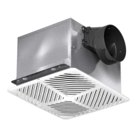
Recommends intake filters for performance and lists maintenance requirements.

Prepare the Fan

Power Assembly

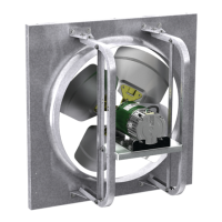
Instructions for installing or securing the fan's power assembly within the housing.

Remove Wiring Knockout

Guidance on removing knockouts for electrical wiring access.

Ductwork

Checking ductwork for horizontal to vertical discharge rotation needs.

Fan Rotation

Steps to rotate the fan housing for different discharge orientations (A Models).

Ceiling Radiation Damper (CRD)

Mounting the Ceiling Radiation Damper

Instructions for attaching the ceiling radiation damper to the fan housing.

Discharge Installation A50-90 Models

Insert Plastic Duct Tab

Step to insert plastic duct tab into box slots for A50-90 models.

Rotate Plastic Duct Adapter

Step to rotate plastic duct adapter until screw tabs meet the box.

Secure Discharge

Step to secure the discharge with provided screws.

Discharge Installation for Ceiling and Inline Exhaust Models Sizes B50-200

Insert Box Scroll Tab

Step to insert box scroll tab into box scroll slots for B50-200 models.

Engage Mounting Tabs

Step to rotate plastic duct adapter to engage mounting tabs into slots.

Optional Ductwork Connection

Optional step to align TR 6x4 adaptor to the 6-inch duct.

Install the Fan

Optimal Location Selection

Guidance on selecting an optimal location for fan installation to ensure best performance.

Mounting Bracket Attachment

Instructions for attaching and adjusting mounting brackets to the fan.

Ductwork Installation Importance

Importance of ductwork installation for fan performance, showing good vs. poor configurations.

Ductwork to Discharge Collar Connection

Steps to slide and secure ductwork over the fan's discharge collar.

Wire the Fan

Wiring Cover Removal

Instructions for removing the wiring cover before electrical connections.

Final Wiring Tidy and Cover Replacement

Final step to tidy wiring and replace the wiring cover after connections.

A50-90-VG and A90-130-VG Fan Models

Internal Switch for Airflow Speed

Explains the internal switch for setting three airflow speeds on specific models.

Whole House Ventilation Two-Speed Operation

Standard Fan Installation

Step 1: Install fan according to standard installation procedures.

Operation with Activated Sensor

Explains fan operation at certified airflow when switch/sensor is activated.

Operation at User Set Low Speed

Describes fan operation at a user-set low speed when switch/sensor is off.

Safety: Power Shut-off for Servicing

Safety instruction to shut off power at the breaker before servicing.

Wiring Diagrams for Ventilation Modes

Continuous Ventilation Wiring

Wiring diagram for continuous ventilation setup.

Continuous Ventilation with Sensors Wiring

Wiring diagram for continuous ventilation with sensors.

Continuous Ventilation with Light & Wall Switch Wiring

Wiring diagram for continuous ventilation with light and wall switch.

Attach the Grille

Accessory and Damper Plug Connection

Connects lighted grille wire to accessory or damper socket.

Grille Attachment and Tightening

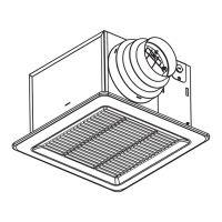
Attaching grille with screws, warning against over-tightening.

Attachment Screw Cover Installation

Sliding attachment screw covers over the attachment screws.

Light Bulb Installation

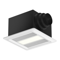
Installing light bulbs into light sockets for fluorescent or LED types.

Lens Installation

Snapping lens into place on the grille.

Final Power On and Operation Check

Turning on power and checking fan and light operation.

Converting from Ceiling to Cabinet Design for Ceiling Exhaust Fans

Conversion Kit Parts List

Lists components included in the conversion kit.

Tools Required

Specifies necessary tools for the conversion process.

Conversion Steps

Detailed, step-by-step instructions for converting the fan design.

General Maintenance Suggestions

Periodic Inspection Recommendation

Recommends periodic inspection (once or twice a year) for optimal performance.

Motor and Wheel Cleaning

Guidance on checking and cleaning dust/dirt buildup on motor and wheel.

Motor Lubrication

Instructions for lubricating motors that have an oil hole provided.

Related product manuals