®
Ceiling Exhaust Fans 1
Document 483971
Models SP-AP0511W and SP-AP0511WL
Ceiling Exhaust Fans
Installation, Operation and Maintenance Manual
Please read and save these instructions for future reference. Read carefully before attempting to assemble, install,
operate or maintain the product described. Protect yourself and others by observing all safety information. Failure
to comply with these instructions will result in voiding of the product warranty and may result in personal injury
and/or property damage.
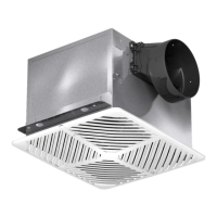
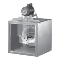
Ceiling Exhaust Fan
Designed for clean air applications where low sound
levels are required. Many options and accessories are
available such as lights, motion detectors, humidity
sensors, CO
2
sensors, and night lights.
Table of Contents
Supplied Accessories ...................... 2
Dimensional Data ......................... 2
Wiring Diagrams .......................... 3
Features ................................. 3
Plug and Play Accessories .................. 4
Installation for New Construction ............. 5
Retrofit Installation ......................... 9
Maintenance ............................. 10
Typical Installation ........................ 11
Our Commitment ...................Backcover
CAUTION!
• For general ventilating use only. Do
not use to exhaust hazardous or
explosive materials and vapors.
• Not for use in cooking areas (Fig. 1)
• This product must be properly
grounded.
WARNING!
To reduce the risk of fire, electric shock, or injury to persons,
observe the following:
• Use this unit only in the manner intended by the manufacturer. If
you have questions, contact the manufacturer.
• Before servicing or cleaning unit, switch power off at service panel
and lock service disconnecting means to prevent power from
being switched on accidentally. When the service disconnecting
means cannot be locked, securely fasten a prominent warning
device, such as a tag, to the service panel.
• Installation work and electrical wiring must be done by qualified
person(s) in accordance with all applicable codes and standards,
including fire-rated construction codes and standards.
• Sufficient air is needed for proper combustion and exhausting
of gases through the flue (chimney) of fuel burning equipment
to prevent back drafting. Follow the heating equipment
manufacturer’s guideline and safety standards such as those
published by the National Fire Protection Association (NFPA),
and the American Society for Heating, Refrigeration and Air
Conditioning Engineers (ASHRAE) and the local code authorities.
• When cutting or drilling into a wall or ceiling, do not damage
electrical wiring or other hidden utilities.
• Ducted fans must always be vented to the outdoors.
• Do not use this fan with any solid state speed control.
• If this unit is to be installed over a tub or shower, it must be
marked as appropriate for the application and be connected to a
Ground Fault Circuit Interrupter (GFCI) protected branch circuit.
• These models are ETL listed for tub and shower enclosures.
• These fans are not to be installed in a ceiling thermally insulated
to a value greater than R40.
45° 45°
Do not install
fan in this area
Fig. 1
General Safety Information
Only qualified personnel should install this fan.
Personnel should have a clear understanding of these
instructions and should be aware of general safety
precautions. Improper installation can result in electric
shock, possible injury due to coming in contact with
moving parts, as well as other potential hazards.
1. Do not install this ventilation fan where interior room
temperature may exceed 104°F (40°C).
2. Make sure that the electric service supply voltage is
AC 120V, 60Hz.
3. Follow all local electrical and safety codes, as well as
the National Electrical Code (NEC) and the National
Fire Protection Agency (NFPA), where applicable.
Follow the Canadian Electric Code (CEC) in Canada.
4. Always disconnect the power source before working
on or near the fan, motor, light fixture, or junction
box.
5. Protect the power cord from sharp edges, oil,
grease, hot surfaces, chemicals or other objects.
6 Do not kink the power cord.
7. Do not install the unit where ducts are configured as
shown in Fig. 2.
8. Provide make up air for properventilation.
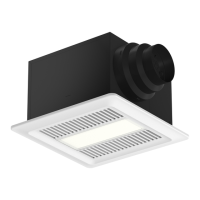
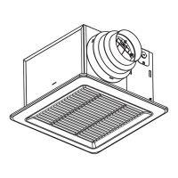
SP-AP0511W
(AV0511DS1)
SP-AAP0511WL
(AV0511DSL1)
SP-AP0511W SP-AP0511WL
Fig. 2
Adaptor