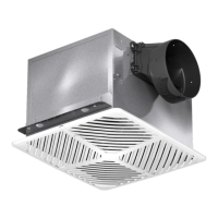
Ceiling Exhaust Fans 5
Installation for New Construction
CAUTION
Please wear gloves during the installation process.
IMPORTANT
Remove the tape from
the damper and adaptor
before installation.
A
C
D
B
USB Receptacle
Fig.2.a
Fig.2.b
Fig.1
11 3/4~22 1/2
(300~579)
4 Screws
(ST4x30)
Tab
Per Bryan M, need image for our
models is needed.
Adaptor
Damper
Tape
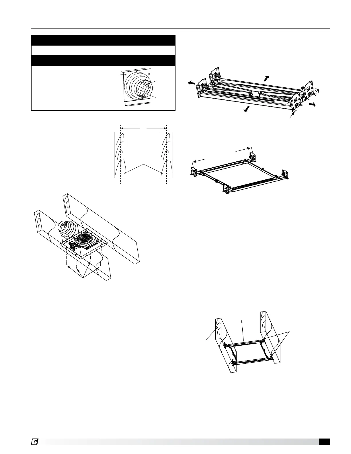
• 12 inches (305 mm)
If the spacing of L is 12 inches
(305 mm) on center, follow the
installation as shown in Fig. 1.
Secure four screws (ST4X30)
at flange of frame to the joists.
Then follow steps 6 through 9
on (pages 6 through 7) to
complete the installation.
• 16 to 24 inches (406 to 610 mm)
If the spacing of L is 16 to 24 inches (406-610 mm),
please use the suspension bracket assembly as shown
in Figures 2a and 2b.
Joist Information
A
C
D
B
USB Receptacle
Fig.2.a
Fig.2.b
Fig.1
11 3/4~22 1/2
(300~579)
4 Screws
(ST4x30)
Tab
Per Bryan M, need image for our
models is needed.
Adaptor
Damper
Tape
Joists
A
C
D
B
USB Receptacle
Fig.2.a
Fig.2.b
Fig.1
11 3/4~22 1/2
(300~579)
4 Screws
(ST4x30)
Tab
Per Bryan M, need image for our
models is needed.
Adaptor
Damper
Tape
Joists
L
Unit: inches (mm)
Fig. 1: 12 inch On Center Joists
A
C
D
B
USB Receptacle
Fig.2.a
Fig.2.b
Fig.1
11 3/4~22 1/2
(300~579)
4 Screws
(ST4x30)
Tab
Per Bryan M, need image for our
models is needed.
Adaptor
Damper
Tape
Joists
L
Unit: inches (mm)
Fig. 2b: Suspension Bracket Assembly
A
C
D
B
USB Receptacle
Fig.2.a
Fig.2.b
Fig.1
11 3/4~22 1/2
(300~579)
4 Screws
(ST4x30)
Tab
Per Bryan M, need image for our
models is needed.
Adaptor
Damper
Tape
Joists
L
Unit: inches (mm)
Fig. 2a: 16 to 24 inch On Center Joists
Suspension Bracket Assembly
Suspension Bracket Installation,
Steps 1 through 11
1. Bend down the eight tabs for positioning as shown
in Fig. 2a and unfold the bracket assembly, Fig. 2b.
2. Attach one side of the bracket assembly to the joists
by drilling 2 captured self-tapping screws (ST4X20).
See Fig. 3.
3. Adjust the length of the bracket assembly by pulling
the unsecured end of the bracket assembly towards
the joist. Attach the unsecured side of the bracket
assembly to the joist by drilling the (2) captured, self-
tapping screws (ST4X20) to the joist. See Fig. 3.
Joist
Screws
(ST4X20)
Active Part
Fig.4
2 Screws
(ST4X30)
Position
of adaptor
Fig.5
Buckle
Fan Body
3 Screws
(ST4x30)
Fig. 3
 Loading...