5
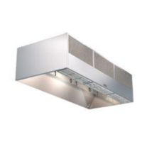
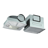
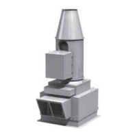
Fire Ready Hood
Preparing the Install Location
Mounting Bracket - The mounting bracket and hood must be centered over the range. If the range is not in place,
the center marking should be relative to it’s final position. Refer to page 7 for bracket mounting points, rear access
holes and access points.
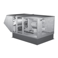
Ductwork - The ductwork and fittings used for outside venting (if applicable) must be carefully selected to ensure
that the static pressure is in line with the fan parameters. The table below displays maximum duct length allowed for
the various fan options.
Hood
Width
NFPA 101
Compliance
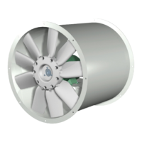
Fan Type Venting
CFM
(at hood)
Duct Length
(maximum)
30 inches
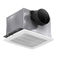
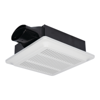
No Internal Front (recirculating) 140 Not applicable
No Internal Rear (recirculating) 250 Not applicable
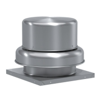
No Inline Duct Fan Vertical Duct 470 35 feet
No Exterior Wall Fan Vertical Duct 150 20 feet
Yes Internal Front (recirculating) 500 Not applicable
Yes Internal Rear (recirculating) 500 Not applicable
Yes Inline Duct Fan Vertical Duct 510 35 feet
Yes Exterior Wall Fan Vertical Duct 550 20 feet
36 inches
No Internal Front (recirculating) 140 Not applicable
No Internal Rear (recirculating) 250 Not applicable
No Inline Duct Fan Vertical Duct 470 35 feet
No Exterior Wall Fan Vertical Duct 150 20 feet
Yes Internal Front (recirculating) 150 Not applicable
Yes Internal Rear (recirculating) 500 Not applicable
Yes Inline Duct Fan Vertical Duct 510 35 feet
Yes Exterior Wall Fan Vertical Duct 550 20 feet
Maximum duct length equals horizontal and vertical duct runs plus duct components such as fittings, elbows, and transitions.
For installations requiring vertical duct venting to an inline fan and NFPA 101 compliance, the hood should be
adapted from a 7-inch round duct access hole to a minimum 12-inch duct.
For installations requiring vertical duct venting to an inline fan and NFPA 101 compliance is NOT required, the hood
can be adapted to a minimum 10-inch duct.
WARNING
The amount of fittings and ductwork directly affects the resistance or static pressure placed on the system. If the
system is not within the proper static pressure range, the heat sensors and controls will be adversely affected and
will impact the proper function of the safety controls. Therefore it is required that airflow testing be recorded along
with installation documentation. The air testing is accessed by the removal of the grease tray and measured with
an airflow pressure gauge.
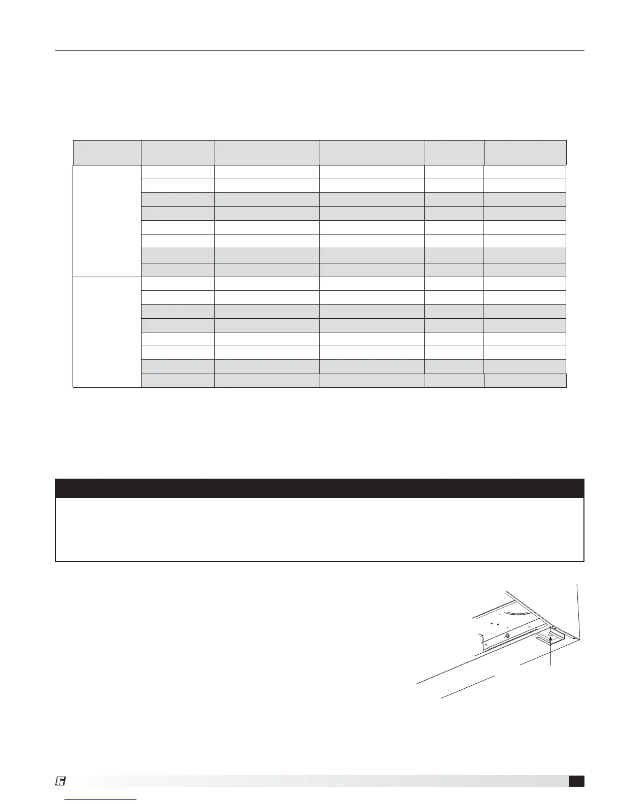
Static Pressure Testing - The magnehelic gauge test port opening is located
beneath the grease tray. The static pressure needs to be measured to ensure
airflows meet design criteria. The airflow is measured by attaching the gauge
tubing to the magnehelic gauge inlet, and the hood fitting is attached to the
grease drain hole beneath the grease tray.
A reading of 0.45 to 0.85 inches wg. is required to meet design standards.
This reading will correspond to the static pressure of the ductwork, hood
and fan combination.
Magnehelic Gauge
Test Port
Magnehelic Gauge
Test Port
®