Indirect Gas-Fired Heat Modules22
Troubleshooting-Ignition Controller
The ignition controller has a diagnostic LED light at
the top right of the controller. The LED light will flash
GREEN for normal operation or RED for an error.
The following are the green LED codes of operation:
The following are the red LED codes of error:
Airflow Fault (6 red flashes)
An airflow fault may occur for the following reasons:
• During the start-up sequence, the controller relay
turned the combustion blower on but the blower did
not prove airflow in 30 seconds.
• During the start-up sequence, the airflow was
proven before the controller turned the combustion
blower on. If this condition lasts for 30seconds, the
control will error out.
To fix fault, determine which error above is occurring,
remove power from controller, fix problem and re-power
controller.
Flame Fault (2 red flashes)
If the main gas valve fails to close completely and
maintains a flame, the full-time flame sensor circuit will
detect it and energize the combustion blower. Should
the main valve later close completely and remove the
flame signal, the combustion will be de-energized.
Ignition lockout (1 red flash for start-up,
4 red flashes for during operation)
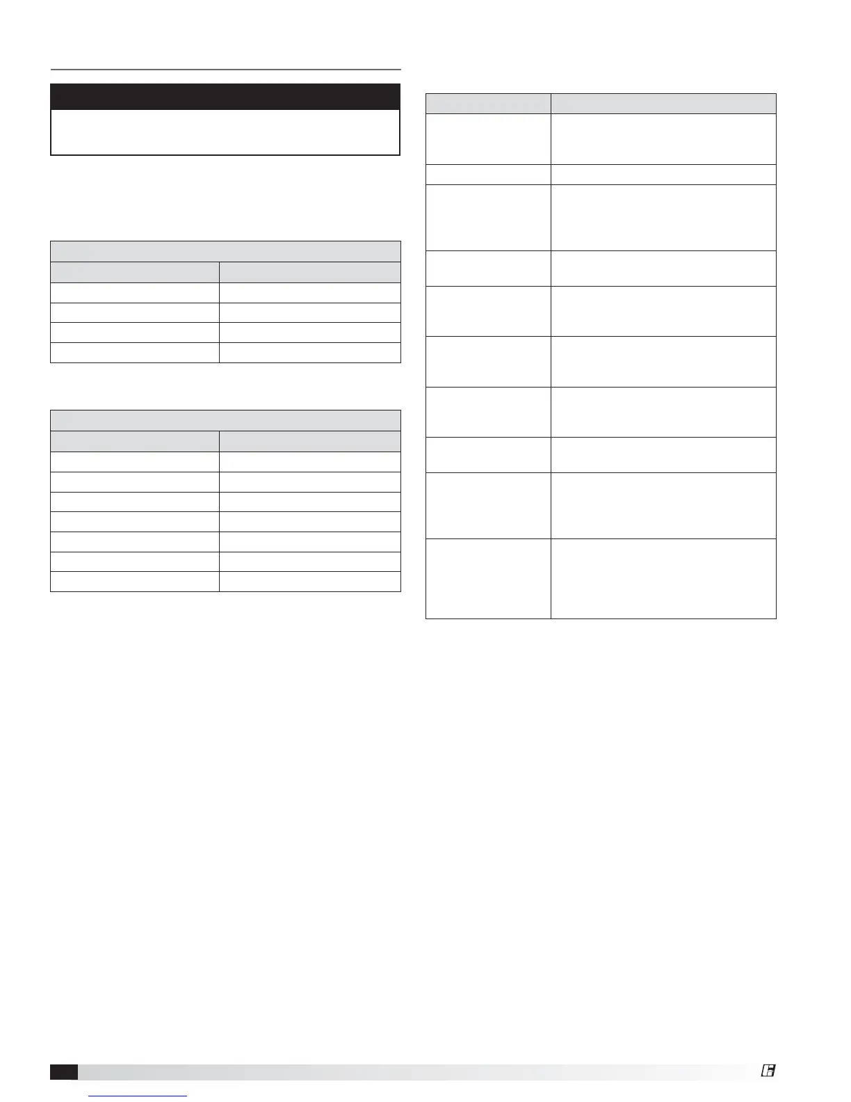
GREEN LED Indications - NORMAL OPERATION
Flash Code Flash Code Indication
Steady on Flame detected, main burner on
0.1 second on/off Controller is sparking
0.5 second on/off Purge or inter-purge time
0.5 second on/4.5 second off Retry or recycle time
Possible Cause Solution
Manual gas valve
not open
Open manual valve. If combination
valves are used, verify that switch on
top is in “ON” position.
Air in the gas line Bleed gas line.
Supply gas pressure
too high or too low
Check that supply pressure is
between 6 and 14 in. wg for natural
gas and between 11 and 14in. wg for
LP gas.
Loose wire
connections
Check for tight wire connections.
No Spark:
a. Spark electrode
Ensure spark gap is 1/8 inch and
ceramic insulator is not cracked.
Replace if necessary.
b. Spark cable
shorted to
ground
Replace spark cable.
c. Ignition
controller not
grounded
Ground ignition controller.
High Limit Control
tripped
Check unit airflow and manifold
pressure.
Faulty combination
valve
Measure voltage between terminals
MV and Common. If 24volts is
present but valve remains closed,
replace valve.
Faulty ignition
control
Check diagnostic LED on controller
for “steady on”. If LED remains on
constantly and there is NO voltage
between V1 and V2, replace ignition
controller.
RED LED Indications - ERROR OPERATION
Flash Code Flash Code Indication
Blinks 1 time No flame in trial time error
Blinks 2 times Flame sense circuit error
Blinks 3 times Valve circuit error
Blinks 4 times Flame loss error
Blinks 6 times Airflow error
Blinks 7 times Ground or internal error
Steady on Line voltage/frequency error
NOTE
The green LED light indicates NORMAL operation
while the red LED light indicates an ERROR operation.
Valve Circuit Error (3 red flashes)
Check that the valve is a 24 volt AC valve. Check that
the valve is wired correctly.
Internal Control Error (7 red flashes)
Check all ground connections including the entire unit.
Line Frequency/Voltage Error (solid red)
Check that the controller power is 24 volt AC
(+10%/-15%). Check for 60 Hz or 50 Hz.
If all checks have been made using the troubleshooting
guide and you have confirmed there are no other
defective components, and the red LED error light is
flashing or on, then the ignition controller may need to
be replaced.
®