Indirect Gas-Fired Heat Modules8
Venting Methods
There are three venting methods for indoor mounted
units. For each method, the units can be vented
horizontally through an exterior wall or vertically
through the roof. Specific venting instructions are
provided for each method and shown in the following
pages. Construct the vent system as shown in these
instructions. Refer to your unit specific submittal to
determine the applicable venting option.
The venting method options are:
Standard Indoor Venting
• uses building air for combustion
• vents exhaust to outdoors
• one exterior roof or wall penetration
Separated Combustion Concentric Venting
• uses outside air for combustion
• vents exhaust to outdoors
• one exterior roof or wall penetration
Separated Combustion 2-Pipe Venting
• uses outside air for combustion
• vents exhaust to outdoors
• two exterior roof or wall penetrations
NOTE
For each method, the units can be vented horizontally
through an exterior wall or vertically through the roof.
Refer to the specific venting instructions for your
unit. Construct the vent system as shown in these
instructions.
Installation of Standard Indoor
Venting
Standard indoor venting uses one penetration through
an exterior wall or roof for venting the flue exhaust.
The combustion air is supplied from the air inside the
building. Units must not be installed in a potentially
explosive, flammable, or corrosive atmosphere. To
prevent premature heat exchanger failure, do not locate
unit where chlorinated, halogenated or acid vapors are
present.
When units are installed in tightly sealed buildings,
provisions should be made to supply an adequate
amount of infiltration air from the outside. The rule of
thumb is that an opening of one square inch should be
provided for every 1000 BTUs per hour of input rating.
Vent terminals must be used. Construct the vent
system as shown in the drawings. Reference the Vent
Pipe Diameter table and Exhaust Vent Pipe table for
additional details.
Installing Exhaust Vent Pipe
Install the vent pipe with a minimum downward slope
(from the unit) of 1/4-inch per foot (horizontal venting
only). Securely suspend the pipe from overhead
structures at points no greater than 3 feet apart.
The minimum vent length is 5 feet for horizontal and
10feet for vertical. The maximum vent length is 70 feet.
The total equivalent vent length must include elbows.
The equivalent length of a
4 inch elbow is 6feet and
the equivalent length of a
6inch elbow is 10 feet.
Attach the vent terminal
to the end of the exhaust pipe.
Vent Pipe Diameter
Select the vent pipe
diameter. Use only the
specified pipe diameter.
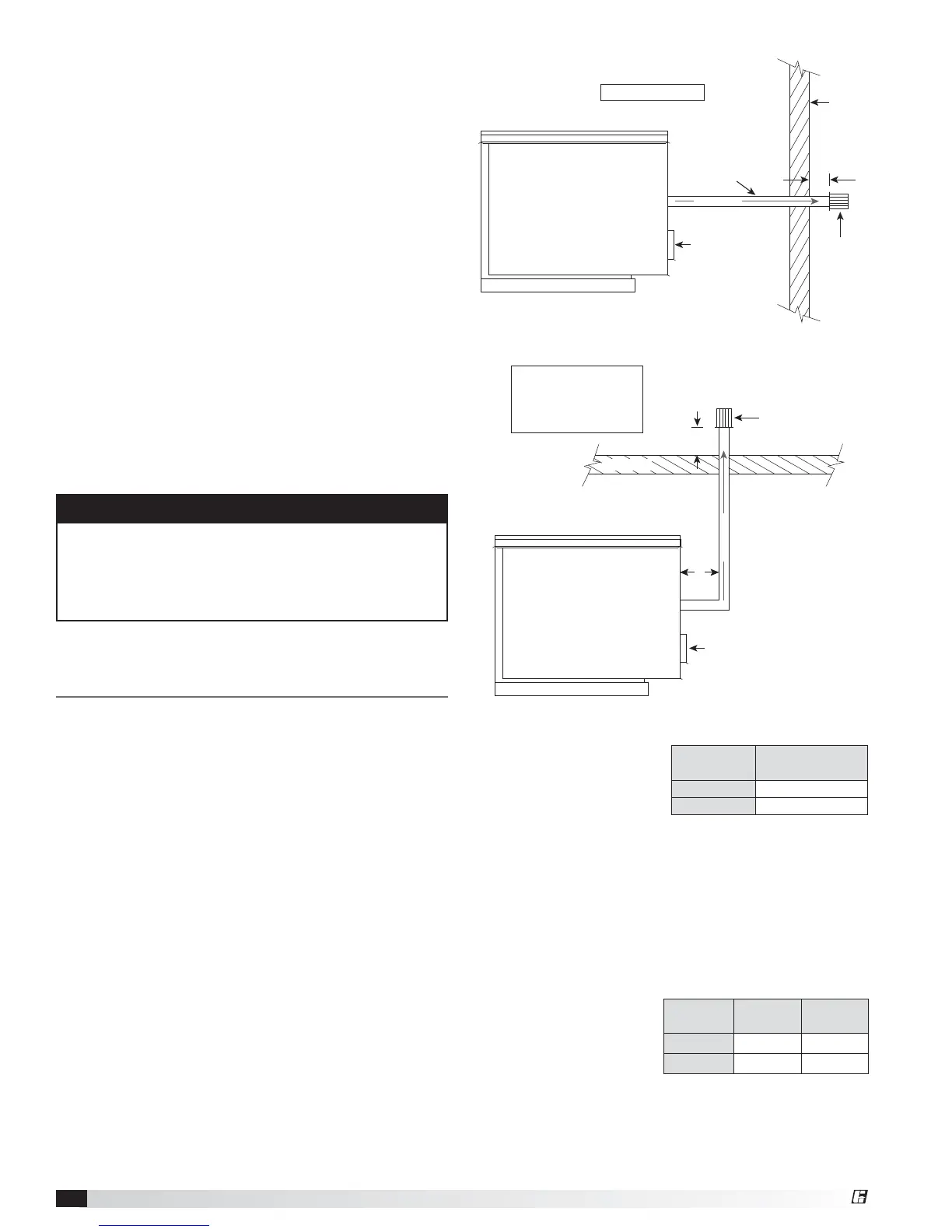
Standard Indoor Venting - Vertical
Standard Indoor Venting - Horizontal
Vent
Length
Minimum
(feet)
Maximum
(feet)
Horizontal 5 70
Vertical 10 70
Furnace Size
(MBH)
Exhaust Pipe
Diameter (inches)
75-175 4
200-400 6
A = 12 inch minimum
Air Inlet
A
Exterior
Wall
Exhaust
Vent
Terminal
Pitch vent pipe
downward
from furnace
¼ inch per foot
EXHAUST
A A
Exhaust Vent
Terminal
EXHAUST
A = 12 inch minimum
B = 12 inch minimum,
but should size
according to expected
snow depth
Air Inlet
B
Roof Line
®