555
®
Series Electric Benders
Greenlee / A Textron Company 4455 Boeing Dr. • Rockford, IL 61109-2988 USA • 815-397-7070
11
Service Instructions (cont’d)
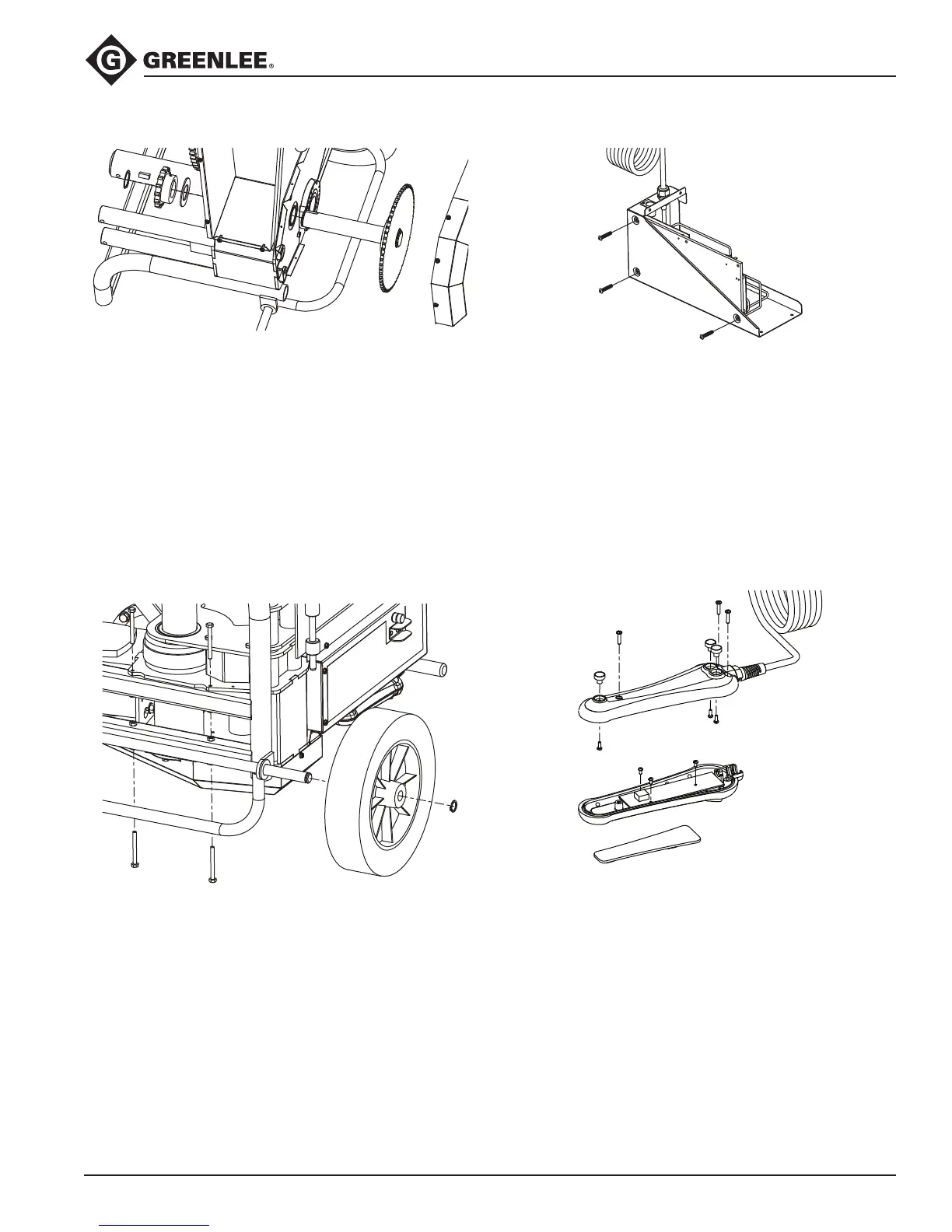
Countershaft
1. Remove seven screws and rear chain guard.
2. Remove connecting link and rear drive chain.
3. Remove the front drive chain (refer to previous
instruction).
4. Remove a retaining ring from the countershaft.
5. Pull off the sprocket, key, and thrust washer.
6. Pull out the countershaft from the opposite side.
7. Remove the other thrust washer, sprocket, and key.
8. Reassemble in reverse order.
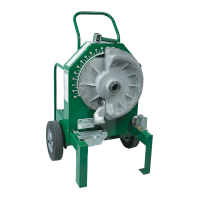
Wheel Base
1. Lay the bender on its back so that the kick bar is
resting on something that will keep the wheels in the
air.
2. Remove the six screws and nuts attaching the lower
base and pull it off the bender frame.
3. Remove a retaining ring from the axle.
4. Remove the wheel and axle.
5. Reassemble in reverse order.
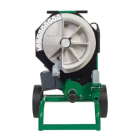
Control Board Assembly
1. Remove outer control box (refer to previous
instruction).
2. Disconnect the power connections to the board
from the circuit breaker and power cord.
3. Disconnect the pendent receptacle cable.
4. Remove the three button head screws attaching
the control board assembly to the enclosure, and
remove the control board assembly and the three
spacers.
5. Reassemble in reverse order.
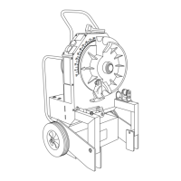
Pendant Switch
1. Remove three screws holding the housing halves
together and separate.
2. Unplug the pendant cord from the circuit board and
remove strain relief from housing.
3. Remove the three screws and the circuit board.
4. Unplug the keypad from the circuit board.
5. Remove the three screws from the bottom housing
to remove the magnets.
6. Peel the keypad membrane from the top housing.
7. Reassemble in reverse order noting the following:
Clean all residue from the mounting surface.