
W
wendyramosJul 30, 2025
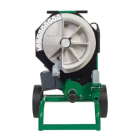
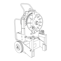
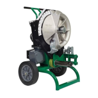
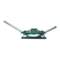
What to do if Greenlee 555 bender will not operate?
- KKaitlyn JonesJul 30, 2025
If your Greenlee Construction Equipment bender isn't operating, first ensure that the switch is turned on. Also, check the supply voltage circuit operation to make sure there is voltage.