Greenlee Textron / Subsidiary of Textron Inc.
8
4455 Boeing Dr., Rockford, IL 61109-2988 815/397-7070
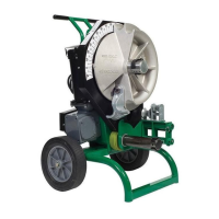
555 Electric Bender
1/2" - 2" Rigid Conduit, Schedule 40 Pipe
and 1/2" - 1-1/4" EMT
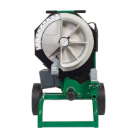
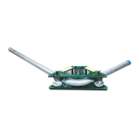
Refer to Setup for mounting selected shoe and support
unit. Mark pipe to desired stub-up length. Note 2" min.
dimension is required as shown in Fig. 4. Other stub-up
Figure 4
Bending Instructions
Figure 5
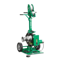
To release the pipe or conduit push the control switch
to the UNLOAD position. Allow shoe to rotate, drop
the unit support (see Fig. 6) and remove conduit
(see Figs. 7 & 8).
Wear eye protection when operating
or servicing this tool.
Failure to wear eye protection can
result in serious eye injury from
flying debris.
Pinch points:
Keep hands away from bending
shoe, rollers and conduit when
bender is in use.
Failure to observe this warning can
result in severe injury or death.
Do not operate the bender while wearing loose
clothing. Loose clothing can get caught in moving
parts.
Failure to observe this warning can result in severe
injury or death.
dimensions can be found in charts on pages 16-25 of
this manual or on the bender decals. At this point, make
sure the shoe is rotated to 5° to 10° before the 0°
setting. After marking the pipe or conduit, place it into
the bender unit as shown in Fig. 4. This requires sliding
the pipe or conduit over the correct size support unit
through the shoe groove and into the hook. Position
Mark 2 at front edge of hook (see Fig. 4).
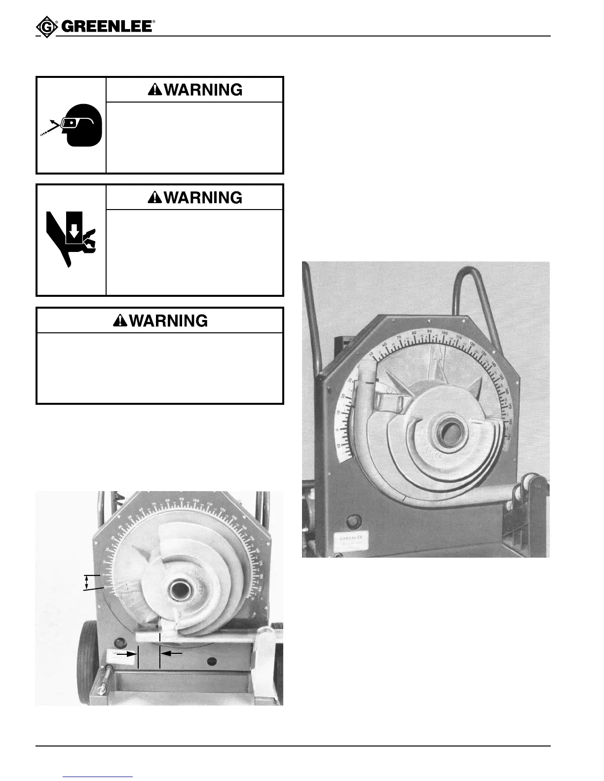
Push the control switch to the BEND position; when the
pointer on the shoe reaches the required bend angle
(Chart B), release the control switch and the bender will
stop (see Fig. 5). Due to springback in pipe/conduit
some overbending is necessary to accomplish desired
bend angle. For this reason Chart B and/or decal on
bender show the required pointer position for desired
bend angle.
5 to 10°
2" minimum