Greenlee Textron / Subsidiary of Textron Inc.
7
4455 Boeing Dr., Rockford, IL 61109-2988 815/397-7070
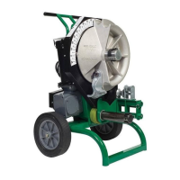
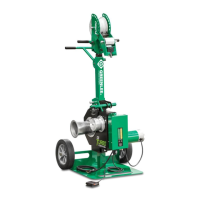
555 Electric Bender
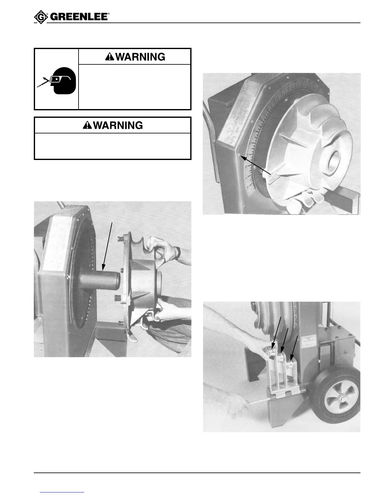
Mounting Bending Shoes
Choose desired shoe size (Rigid; IMC; EMT) and slide it
onto the main shaft as in Fig.1.
Setup
Next, align the four drive studs on the back side of shoe
(Fig. 2) with the 4 holes in the main drive sprocket. Push
the shoe onto the main drive sprocket.
Figure 1
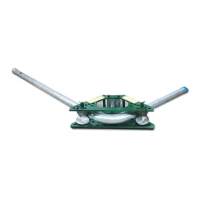
Mounting Support Roller and Support Units
Choose desired support roller or support unit and
corresponding shoe size (Rigid; IMC, EMT).
Mount the support roller or support unit on the right leg
of the bender as you face the unit. Secure the support
roller or unit with the quick release hinge pin (see Fig. 3).
Figure 3
Figure 2
Wear eye protection when operating
or servicing this tool.
Failure to wear eye protection can
result in serious eye injury from
flying debris.
Unplug the bender before changing accessories.
Accidental start-up can result in serious injury.
Main Shaft
1/2 & 3/4
1-1/4
1