Greenlee Textron / Subsidiary of Textron Inc.
14
4455 Boeing Dr., Rockford, IL 61109-2988 815/397-7070
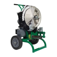
555 Electric Bender
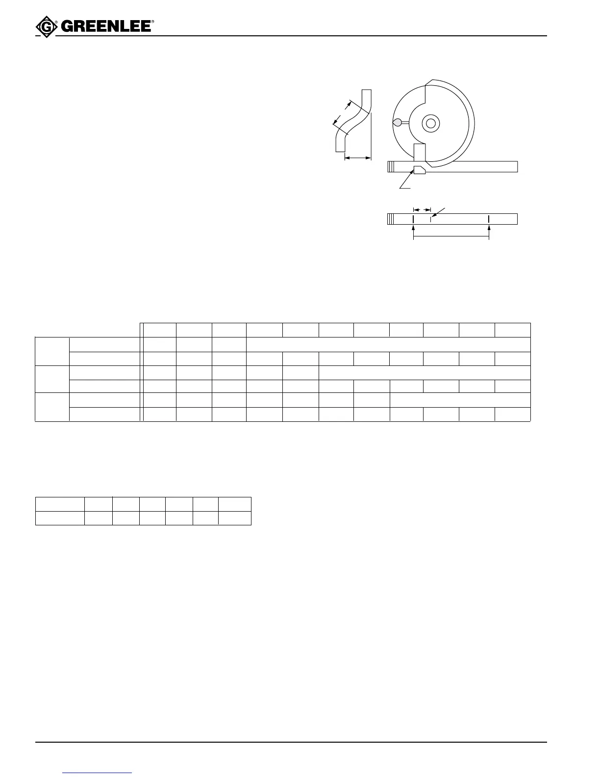
To Find Bending Marks - Offset
1. Measure distance from end of conduit to start of
bend and mark conduit (Mark 1).
2. Refer to Chart D for measurement “X”. Measure this
distance from Mark 1 only and place Mark 2 on
conduit.
3. Refer to Chart C for distance between marks.
Measure this distance from Mark 2 and place
Mark 3 on conduit.
4. Layout of bends is now complete. Next, place
Mark 2 in line with front edge of the shoe hook and
make first bend.
5. Rotate conduit 180 degrees. Place Mark 3 in line
with front edge of shoe hook and complete second
bend.
Front Edge of Hook
Offset
Mark 2 Mark 3
Mark 1
A
X
Chart D
CONDUIT SIZE 1/2 3/4 1 1-1/4 1-1/2 2
“X” 3-1/16 3-1/16 3-3/16 4 4-1/4 4-1/2
Figures are approximate
OFFSET ➤ 246810121416182022
Max Conduit Size 3/4 1-1/2 2 2 and smaller
Center-to-Center 7-3/4 15-7/16 23-3/16 30-15/16 38-5/8 46-3/8 54-1/16 61-13/16 69-9/16 77-1/4 85
Max Conduit Size 3/4 1 1-1/2 2 2 and smaller
Center-to-Center 8 12 16 20 24 28 32 36 40 44
Max Conduit Size 1/2 1 1-1/4 1-1/2 2 2 and smaller
Center-to-Center 8-1/2 11-5/16 14-1/8 16-15/16 19-13/16 22-5/8 25-7/16 28-1/4 31-1/8
Figures are approximate
15°
30°
45°
Chart C
To locate the center-to-center distance of offset bending marks other than those listed in the offset chart, the following multipliers
should be used; multiply the height of offset required by 3.86 on 15° bends, 2 on 30° bends and 1.4 on 45° bends.