Greenlee Textron / Subsidiary of Textron Inc.
33
4455 Boeing Dr., Rockford, IL 61109-2988 815/397-7070
555 Electric Bender
Electrical Component—
Removal and Replacement
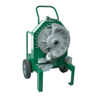
A. Removal of Control Module
1. Disconnect 15 pin connector.
2. Remove six mounting screws.
3. Carefully pull the board out.
B. Removal of Power Module
Note: Step A is not required to remove
power module.
1. Remove black wire from circuit
breaker. Remove white and black
motor wires from AK1 and AK2 and
the wire nut between the white power
wire and the white power module
wire.
2. Remove the 3 wire nuts from the red,
white, and black wires between the
pendant switch and the 15 pin
connector.
3. Remove 5 mounting screws.
4. Unplug 15 pin connector if necessary.
Carefully remove module.
Note: Module will tend to adhere to
the control box panel due to its
coating of thermal grease.
C. Replacement of Power Module
1. Cover rear surface of power module
with thermal grease. Use Thermalloy
Thermalcote 1 or equivalent.
2. Install the module in the control box
and replace the 5 mounting screws.
3. Connect black power cord wire to the
circuit breaker and the white power
cord wire to the power module filter
white wire with a wire nut. Connect
white motor wire to AK1 of SCR
block, and black motor wire to AK2
of SCR block.
Note: Do not reverse the white and
black motor wires.
4. Connect the red, white, and black
wires from the pendant switch to the
red, white and black wires respec-
tively of the 15 pin connector, using
wire nuts.
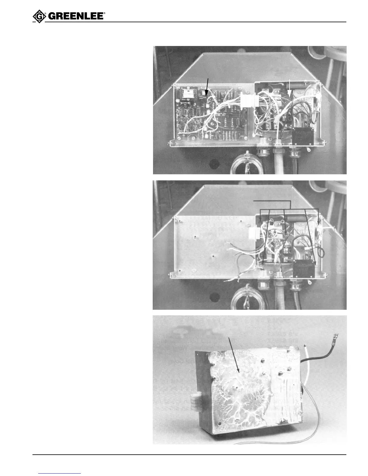
Power Module - Front 503 4140.5
To remove power module -
remove 5 mounting screws
Note: Removal of
control module not
necessary to remove
power module.
Control Module
503 5411.6
Control Box (with cover removed)
503 0374.0
Power Module
503 4140.5
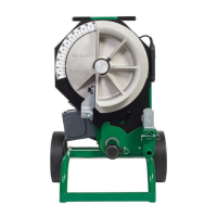
Note: When replacing power
module, thermal conductive
compound must be liberally
applied to entire surface. Use
Theralloy Thermalcote 1 or
equivalent.
Power Module - Rear
503 4140.5