Greenlee Textron / Subsidiary of Textron Inc.
32
4455 Boeing Dr., Rockford, IL 61109-2988 815/397-7070
555 Electric Bender
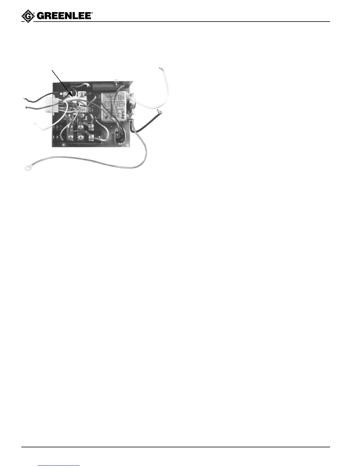
C. Power Module Analysis
If the amber and green LEDs in the control module light
when the pendant switch is held in BEND or UNLOAD
position, but the motor does not run, then the power
module and motor should be tested as follows:
1. With the power plug disconnected, remove the white
and black motor leads from terminal AK1 and AK2
on the SCR block. With the use of a multimeter
tester, read the resistance between the white and
black leads from the motor. If the resistance be-
tween the two leads is greater than one ohm, the
motor either has brushes that need to be replaced or
the motor is “burned out.” Replace parts as needed.
Note: Replacement by user of individual
components on Control, Auto Bend or
Power circuit boards will void the warranty
on the 555.
2. With a resistance of less than one ohm across the
motor leads, the probable cause of malfunction is
likely to be a defective power module. Burnt-out
electronic parts on the power module are often
located by observing sooty spots on the parts. If
any components are believed to be defective, return
the complete unit to a Greenlee authorized service
center for servicing. Do not unsolder components
from the power module board.
3. If the red LED operates, but coasts to a stop rather
than stopping quickly, the dynamic brake is not
functioning, and the power module should be
replaced.
4. If the gold one ohm resistor appears damaged,
replace power module or return bender to a
Greenlee authorized service center.
Power Module - Front
503 4140.5
SCE