555
®
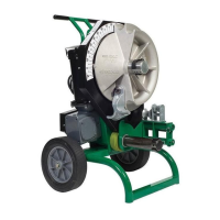
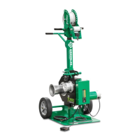
Series Electric Benders
Greenlee / A Textron Company 4455 Boeing Dr. • Rockford, IL 61109-2988 USA • 815-397-7070
7
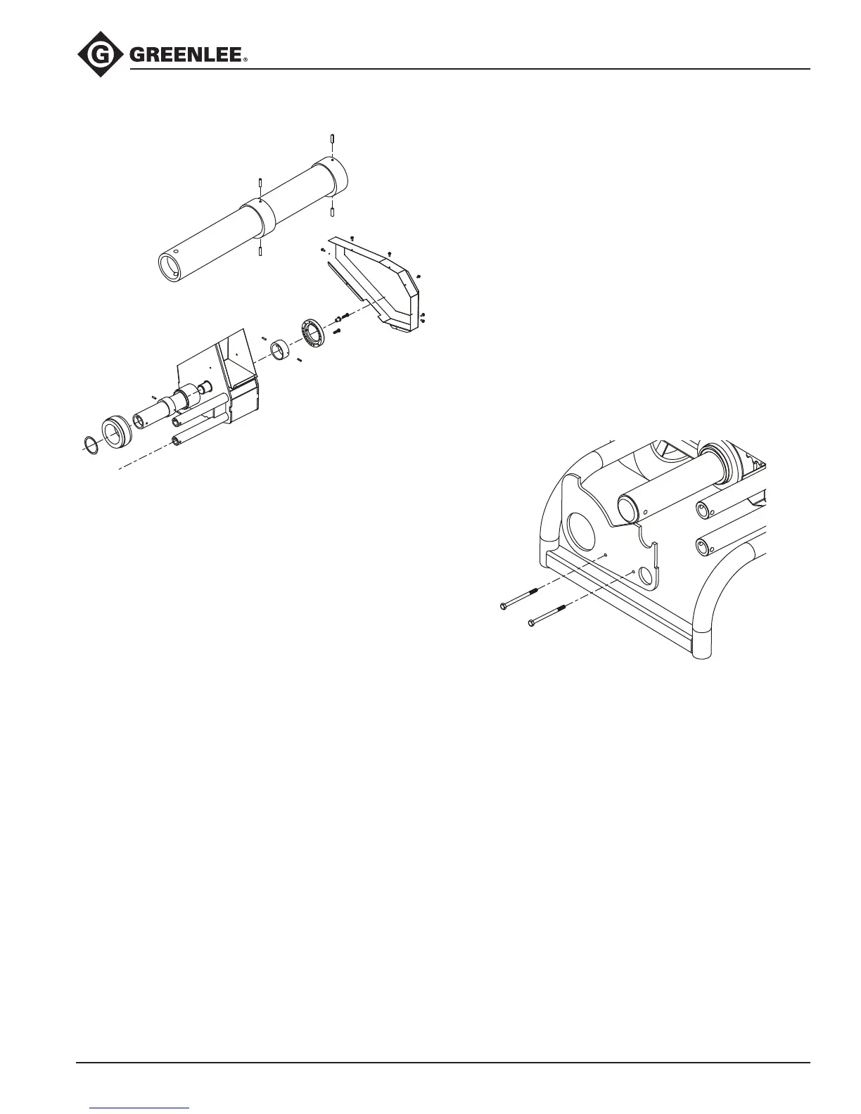
52046889 Eccentric Roller Shaft
1. Remove any support rollers from shaft.
2. Remove the ber thrust washer from the front of the
shaft.
3. Remove seven screws and rear chain guard.
4. Remove two screws securing squeeze adjuster and
the retainer on the top screw. Note which hole the
lower screw is in.
5. Remove the adjuster.
6. Remove the rollpins by driving them into the ID of
the shaft.
7. Pull out the shaft from the front and the rear eccen-
tric from the rear.
8. Remove the front eccentric same as the rear if
needed.
9. Reassemble in reverse order noting the following:
a. Slide the front eccentric over the shaft so the
3/16" holes are closest to the rear.
b. Drive the rollpins into the holes so that they do
not protrude.
c. Lubricate the eccentrics with molybdenum
grease.
d. Insert the shaft into the frame from the front.
e. Insert the rear eccentric into the frame and over
the shaft so the 3/16" holes are visible.
f. Align the holes in the eccentric and shaft
together, making sure that thick part of both
eccentrics are oriented together.
g. Drive the rollpins into the holes, leaving 1/4"
protruding on both sides.
h. Orient the shaft so that the thick part of the
eccentric is at 3 o’clock as viewed from the rear
of the bender.
i. Place the adjuster over the rear eccentric so that
the original hole used is on the right side.
j. Insert the hex screw through the retainer so
screw head abuts the ange and screw into the
top hole.
k. Insert the second screw into the original hole
and rotate the shaft until the screw can be
threaded into its hole.
Roller Stop Plate
1. Remove any roller support assemblies and shoe.
2. Remove the two screws and nuts securing the roller
stop plate.
3. Slide the roller stop plate off the shafts.
4. Reassemble in reverse order.
Service Instructions (cont’d)