Greenlee / A Textron Company 11 4455 Boeing Dr. • Rockford, IL 61109-2988 USA • 815-397-7070
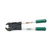
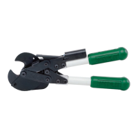
763 and 764M4 Ratchet Cable Cutter
Maintenance (cont’d)
Assembly (cont’d)
7. Place top housing plate (23) over tool assembly,
using spare 3/8" screw and release pin (27) for
alignment. Assemble nuts (18) loosely to hold
housing in place.
8. Lubricate gear shaft (26) and assemble in place of
3/8" spare screw.
9. Assemble retaining ring (9) to gear shaft (26).
10. Assemble bumpers (10) to pin (27).
Note: To replace jaws, see steps 11-18; also see
Figure 5 and exploded view. To replace entire cutter head
(38), skip steps 11, 12, and 15.
11.
Assemble spring (5) to movable jaw (3) using stud (7).
12. Assemble screw (2) and nut (8) into movable jaw (3).
13. Reconnect spring (5) to housing (13).
14. Assemble fixed jaw (1), movable jaw (3) and spacer
(4) into housing assembly using lubricated bolt (25),
nut (6) and two nut retainers (24).
15. Assemble jaw anchor screw (21).
16. Tighten nut (6) to a maximum jaw clearance of
.2 mm (0.007"). To achieve .2 mm (0.007") clearance,
tighten nut (6) snugly so that jaws are against each
other. Then back off nut to the first open slot aligned
with the drive pin hole. There should be not more
than .2 mm (0.007") gap between blades. Operate
the cutter to ensure that the jaws move freely.
17. Bend tab (5) on nut retainer (24) to secure nut (6).
18. Apply adhesive Loctite 416 Super Bonder sparingly
to assemble two bumpers (10) (see Figure 1).
3
7
5
25
6
24
Figure 5
 Loading...