18
Measurements on Three-Phase Circuits (cont’d)
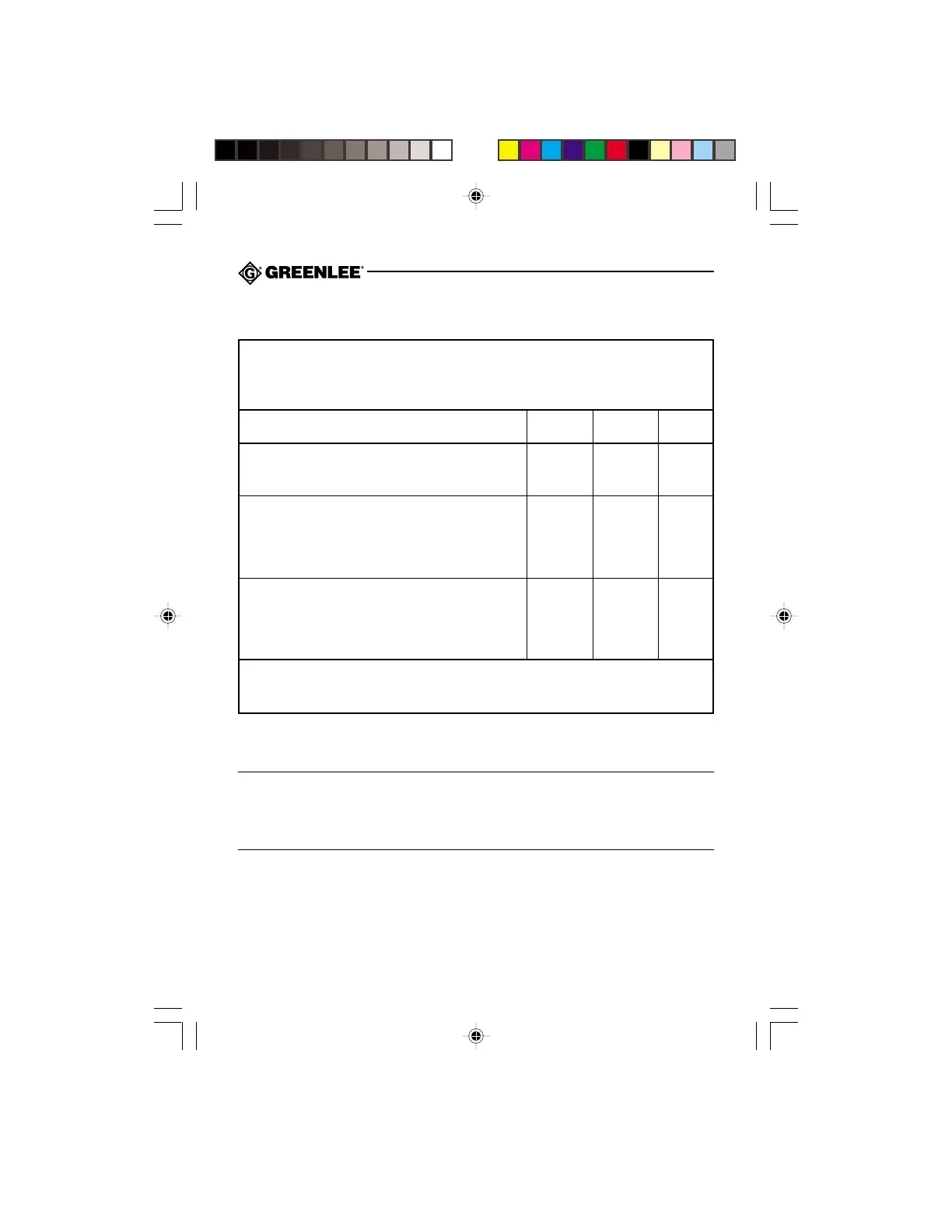
Three-Phase Four-Wire Circuits: Settings Table
*A positive (+) PF indicates an inductive load. A negative (–) PF indicates a capacitive load.
Power factor value is correct for balanced loads only.
**Jaw should be closed and removed from circuit whenever DCA/W ZERO is pressed.
Notes:
• The + sign on the jaw must face the power source.
• All three power measurements (W
R
, W
S
and W
T
) should be positive. Check test lead
connection and clamping of jaw if any power measurement is negative.
Measurement: True Power, Power Factor*, Apparent Power and Reactive Power
(W, PF, KVA and KVAR)
Type of Circuit: 3ø4W
Selector Setting: 3ø4W
Instructions
Red Lead Black Lead Clamp
Connection Connection Location
“R” will flash on the display. Press DCA/W ZERO**.
Connect the leads and position the clamp as shown R N R
to take the first measurement (W
R
/ PF
R
).
After the measurement stabilizes, press READ NEXT.
“S” will flash on the display. Remove clamp from wire.
Press DCA/W ZERO** and connect the leads and S N S
position the clamp as shown to take the final
measurement (W
S
/ PF
S
).
After the measurement stabilizes, press READ NEXT.
“T” will flash on the display. Remove clamp from wire.
Press DCA/W ZERO** and connect the leads and T N T
position the clamp as shown to take the final
measurement (W
T
/ PF
T
).
After the final measurement stabilizes, press READ NEXT. The CMP-200 will calculate and
display the power factor (PF) and true power (W). Press 3ø KVAR KVA to display the
reactive power (KVAR) and apparent power (KVA).