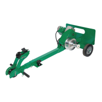
G3 Tugger
®
System
Greenlee / A Textron Company
8
Specifications
Weight .......................................................................................................123 lb (56 kg)
Dimensions
Length ................................................................................................. 1.4 ft (0.43 m)
Width ................................................................................................. 1.95 ft (0.59 m)
Height .................................................................................................. 4.5 ft (1.37 m)
Motor ............................................................................... 120 VAC, 50/60 Hz, 12 amps
Speed (high)
No Load..................................................................................... 97 ft/min (30 m/min)
500 lb ........................................................................................ 59 ft/min (18 m/min)
1000 lb ...................................................................................... 36 ft/min (11 m/min)
Speed (low)
No Load..................................................................................... 41 ft/min (12 m/min)
1000 lb ........................................................................................ 21 ft/min (6 m/min)
2000 lb (intermittent – 5 min on, 20 min off) ................................ 13 ft/min (4 m/min)
Puller Operation—Capstan
Low Speed ....................................................................................................5 wraps
High Speed ...................................................................................................4 wraps
Pulling Rope ........................................................1/2" double-braided composite rope
10,000 lb average breaking strength
Planning the Pull
• Pull in a direction that will require the lowest amount
of pulling force.
• Plan several shorter pulls rather than fewer longer
pulls.
• Locate the puller as close to the end of the conduit
as possible to minimize the amount of exposed rope
under tension.
• Place each component so that the pulling forces are
used effectively.
• Select an anchoring system: adapter sheaves, which
are preferred, or the oor mount.
• Verify that each component has the proper load
rating.
• Inspect the structural supports. Verify that they have
enough strength to withstand the maximum forces
that may be generated.
www.GlobalTestSupply.com
Find Quality Products Online at: sales@GlobalTestSupply.com