Page 8SKU 97079 For technical questions, please call 1-800-444-3353.
BASIC SPECIFICATIONS
Fuel
Type
89+ octane unleaded
gasoline
Capacity 1.98 Gallons
Engine Oil
Type
SAE 30W
(above 32° F)
SAE 5W-30
(at 32° F or below)
Capacity 20 Ounces
Run Time @ 50% Load 7.5 Hours with full tank
Note: Additional specications found in
the TECHNICAL ENGINE SPECIFI-
CATIONS chart in this manual.
The emission control system for this
engine is warranted for standards set by
the U.S. Environmental Protection Agency
and by the California Air Resources Board
(also known as CARB). For warranty
information, refer to the last pages of this
manual.
At high altitudes, the engine’s carbu-
retor, governor (if so equipped), and any
other parts that control the fuel-air ratio will
need to be adjusted by a qualied me-
chanic to allow efcient high-altitude use
and to prevent damage to the engine and
any other devices used with this product.
UNPACKING
When unpacking, check to make sure
that the item is intact and undamaged. If
any parts are missing or broken, please
call Harbor Freight Tools at the number
shown on the cover of this manual as soon
as possible.
SET UP INSTRUCTIONS
Read the ENTIRE IMPORTANT
SAFETY INFORMATION
section at the beginning of this
manual including all text under
subheadings therein before set
up or use of this product.
Risk of accidental
starting; resulting
in serious personal injury.
Turn the Power Switch of the
equipment to its “OFF”
position, wait for the engine to
cool, and unplug the spark
plug wire(s) before
assembling or making any
adjustments to the equipment.
Note: For additional information regarding
the parts listed in the following pages,
refer to the Assembly Diagram near
the end of this manual.
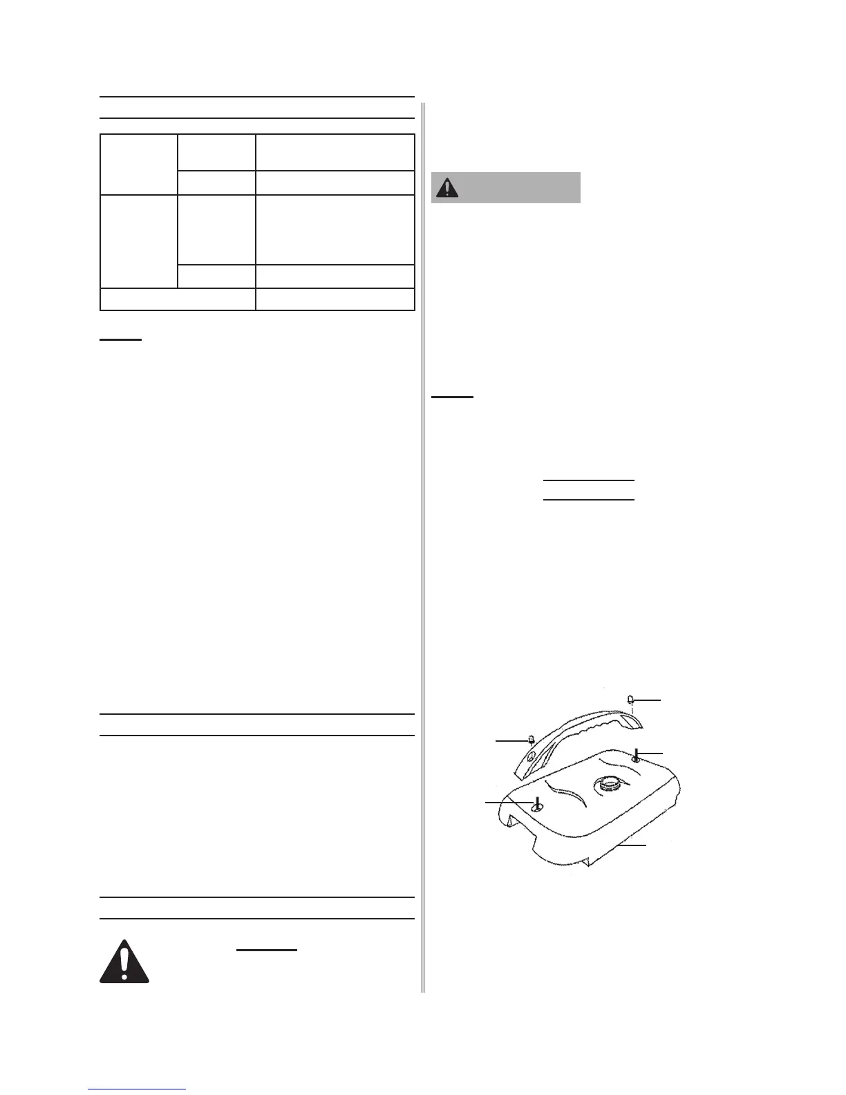
Assembly
Prior to use, the Handle (194) must 1.
be attached to the top of the Fuel
Tank (193). To do so, insert the two
mounting holes at the ends of the
Handle onto the two threaded Bolts
at the ends of the Fuel Tank. Secure
the Handle to the Fuel Tank, using
two Nuts (195). (See Figure A.)
NUT (195)
NUT (195)
FUEL TANK (193)
BOLT
BOLT
FIGURE A
2. Prior to each use, the Generator must
be properly grounded at its Earth
Terminal Set (142). CAUTION! A
licensed electrician only should
WARNING