Telephonics Corporation
R ADAR SYSTEMS D IVISION
TM113806 (3/10) 2-19/2-20 blank
1
Aircraft
2 345891011 12 13 14 15 1667 17 18 19 20 21 22 23
C
28 VDC 15 A
ACFT GND
FAN CONTROL
AB D
1 14
A2 A1
DA
CB GND
20G
20G
20G
37
B
M
P1001
DA-1503B
P2001
RT-1501A
P3001
IN-1502R
MT-1508A
P6001
SYSTEM ON / OFF
10
4
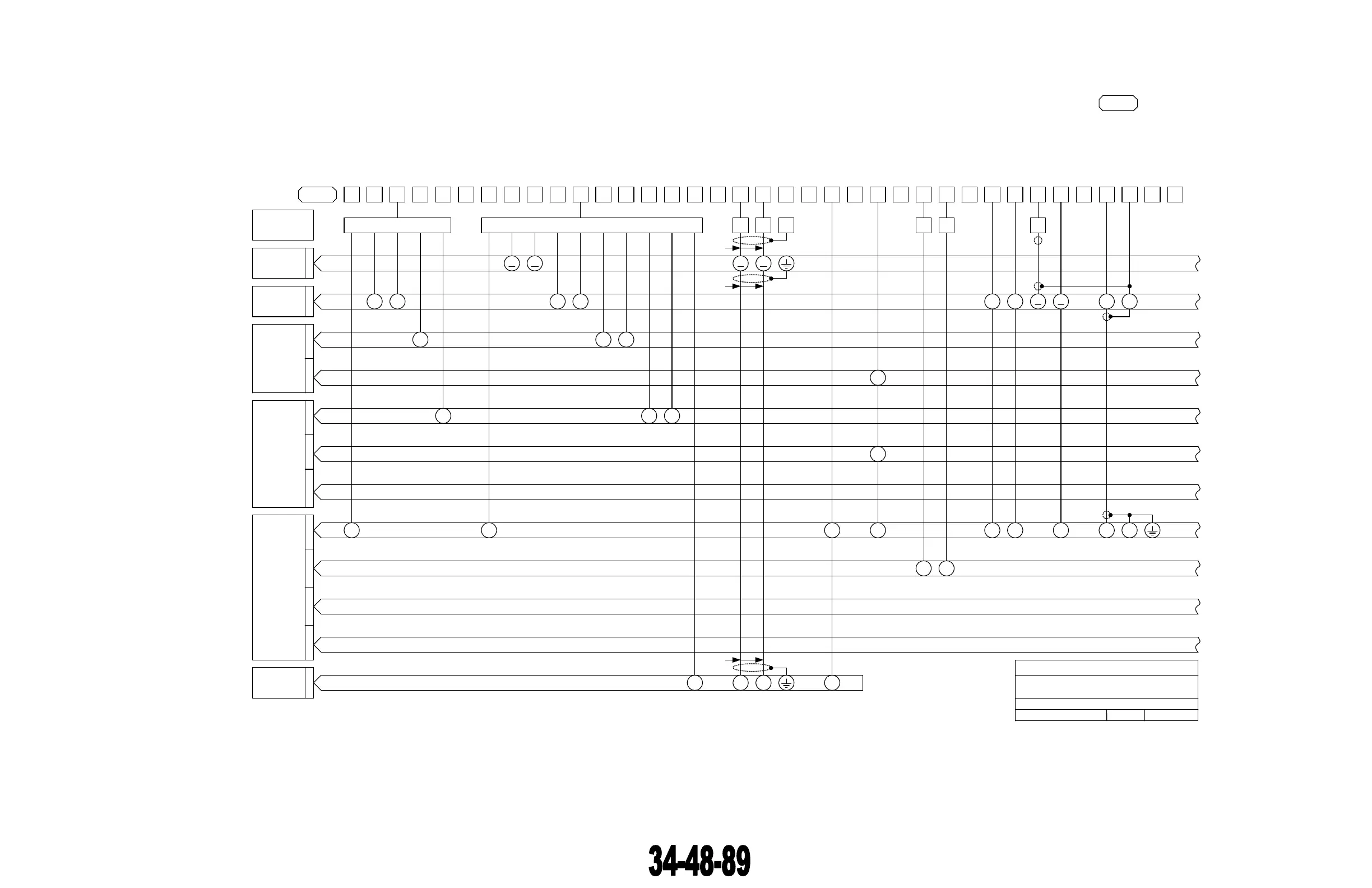
RDR-1700A System Wiring Diagram
364-0000-002 Configuration
Telephonics
Date: 30 April 2007 Rev: G Page 1 of 4
Part Number: WD 364-0000-002
NOTE 2
SHIELD
SPARE
WEIGHT ON WHEELS
WOW RETURN
E
115 VAC 400 HZ HI 2A
115 VAC 400 HZ LO
CB
P Q
11 12
P3002
15
16G
16G
20G
20G
20G
20G
20G
20G
SPARE
SPARE
SPARE
P3004
IN-1702A
P3005P3006
R
20G
24 25
20G
1
26 27
14 15
20G
20G
RT ON/OFF
RT MONITOR
G
26
T
24
30 31 3229
A B
22
28
SPARE
SYS TRIGGER
TRIG SHIELD
N P
10 11
NOTE 4
RG-58C/U
33 34 35
SPARE
SPARE
36
SPARE
37
P5001P5002
IU-1507B
P5003P5004
10
Figure 2.4.1-9 RDR-1700A
Radar System Inter-wiring Diagram
(Page 1 of 4)
The document reference is online, please check the correspondence between the online documentation and the printed version.