10
2.
2.
2.
2. Bo
Bo
Bo
Bo ttom
ttom
ttom
ttom Panel
Panel
Panel
Panel Assembly
Assembly
Assembly
Assembly
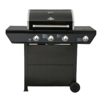
a) Loosen, but do not remove the screws that
are pre-assembled on the side of the Bottom
Panel (B), align the holes on the Cart Leg,
Front Left (F) and Cart Leg, Back Left (G), then
place the Cart Legs onto the screws that were
loosened in the Bottom Panel (B). As shown in Fig. 4 .
b) Tighten the screw from outside to inside, there is
a hole in the outside of the cart leg. As shown in
Fig. 4 .
c) Repeat step 2a and 2b to attach right legs to the
bottom panel making sure all screws are tight.
d) Secure the T ank B olt (Q) to the bottom panel (B). As
s how n in Fig. 4.
3.
3.
3.
3. Triangle
Triangle
Triangle
Triangle Bracket
Bracket
Bracket
Bracket Assembly
Assembly
Assembly
Assembly
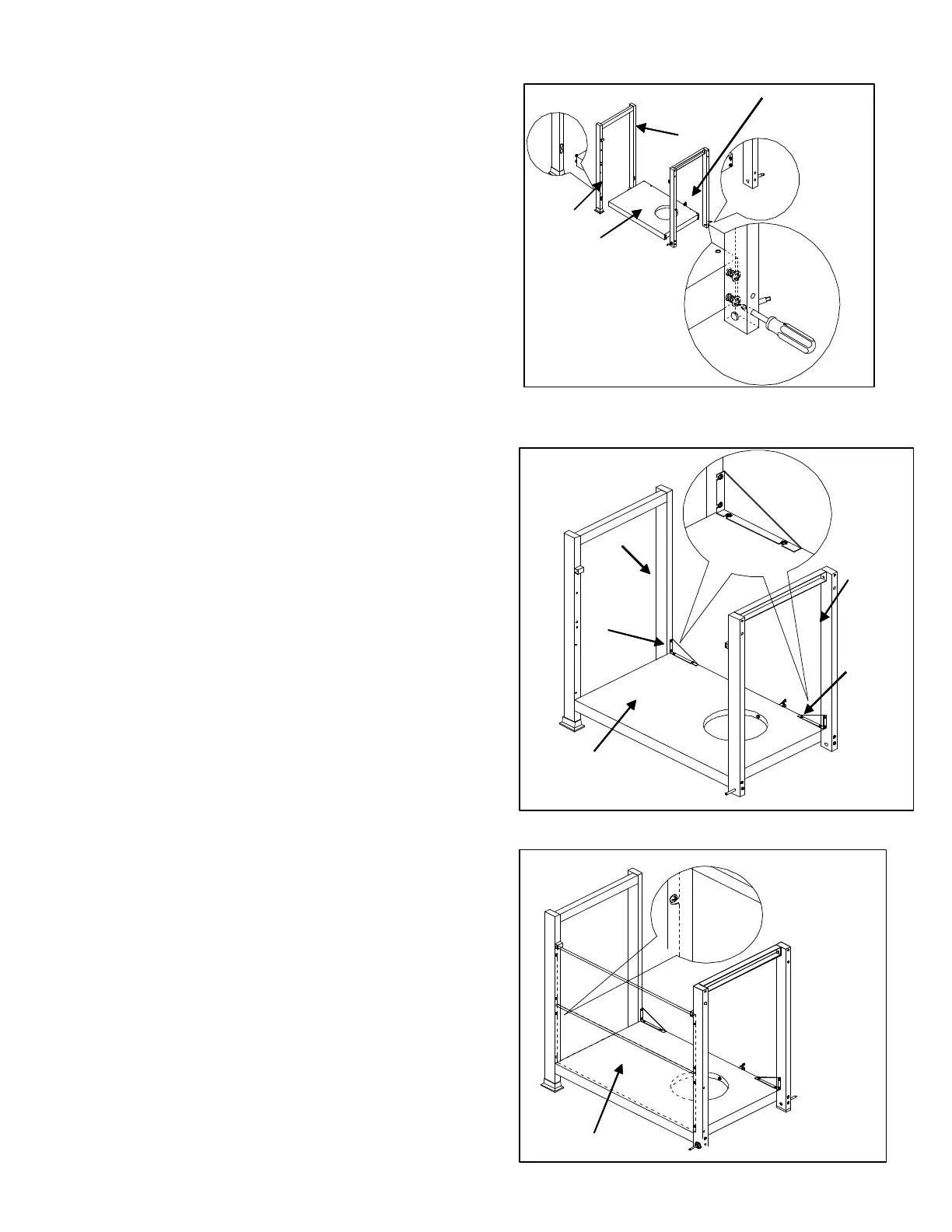
a) Loosen , but do not remove four screws on Bottom
Panel (B), two screws on Cart Leg, Back Left (G)
and two screws on Cart Leg (J), Back Right. Align
the holes of the Triangle brackets with the screws
in the Bottom Panel ( B ) and Cart Leg, Back Left ( G )
and Cart Leg, Back Right ( J ) to connect Triangle
Bracket , Left and Right ( O, P ) to Cart Leg, Back
Left ( G ) and Cart Leg, Back Right ( J ). As shown
in F ig . 5.
b) Tighten the screws .
Note: The flat portion of the triangle should face the
rear of the grill.
4.
4.
4.
4. Front
Front
Front
Front Panel
Panel
Panel
Panel Assembly
Assembly
Assembly
Assembly
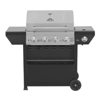
a) Loosen, but do not remove the screws which
are pre-assembled on the cart legs, align the
holes of the bottom front panel ( S ) with the screw
in the legs, then place the front panel ( S ) onto
the screws in the cart legs. As shown i n Fig. 6 .
b) Tighten the screws that were loosened in step 4 a.
Note: Flat facing side of the front panel (S)
should face out.
c) Repeat steps 4 a and 4 b to assemble the to
front panel (S).
Fig.
Fig.
Fig.
Fig. 4
4
4
4
S
Fig.
Fig.
Fig.
Fig. 5
5
5
5
G
B
F
Fig.
Fig.
Fig.
Fig. 6
6
6
6
P
O
B
G
J
Q