Manual EDM 180
Revision 1.0 29.03.2010 Page 25/61
3.9 RS-232 interface
The serial interface exists out of a 9 pin socket which is located on the rear side of the device (labelled
with “RS-232 to PC”). Via this interface the communication of a PC with the instrument happens. The
second interface is behind the front door and is supposed for the service. Above the interface is an LED
which indicates an established connection when shining green. Red signalizes data transfer. Only the RS-
232 cable (catalogue number 1.141 or1.143E) must be used for the connection. The service socket will be
treated preferably when the handshake lines are put on high (CTS or DTS) by the terminal program.
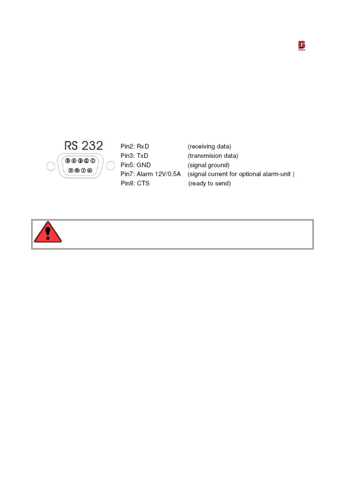
Figure 4: Pin alignment of the socket at the dust monitor „RS-232 to PC“
Only use the original GRIMM data cable due to the alarm output at the 9 pin RS-232 Subminiatur-
socket!
3.10 Calibration label
The calibration label on the rear side of the device shows how long the calibration is valid. After expiration of
validity GRIMM does not warrant any accuracy of the measurements. This is also applicable if the calibration
sticker is damaged or removed.
3.11 Alarm and error messages
Exceeding the set alarm treshold and at occurring device errors (e.g. volume flow control „not ok“) an error
text will be output on the LCD display and a warning sound will resound. The errors will also be stored with
the data sets on the storage card and output via the RS-232 interface. For the meaning of the error
messages see also chapter 9 (RS-232 interface).
 Loading...