76
GB
General Description
The illustration how to handle the
appliance can be found on page
2-3.
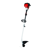
Summary
1 Engine housing
2 Spark plug connector
3 Fuel pump
4 Air lter cover
5 Choke lever
6 Fuel tank
7 Starter handle with starter cable
8 Lifting ring for carrying strap
9 Throttle lock
10 Throttle
11 On/o switch
12 Multifunction handle
13 Anti-vibration handle
14 Top shaft tube
15 Tube xing screw
16 Bottom shaft tube
17 Thread cutter
18 Protective cover
19 Reel capsule
20 Thread reel
21 Carrying strap
22 Maintenance key
Functional Description
The manually operated and portable pet-
rol brusth trimmer is driven by a combus-
tion engine, which operates without inter-
ruption during the work.
The power transmission is by means of a
clutch disc, which transmits the output to
the cutter via a centrifugal clutch at high
speed.
The equipment has an automatic double-
thread reel as the cutter.
In the cutting process, two plastic wheels
rotate about an axis vertical to the cutting
level. To protect the user, the equipment
has a protective device, which covers the
cutting device.
Please refer to the descriptions below for
how the operating parts work.
Safety Functions
9 Throttle lock
Prevents accidental accelera-
tion of the engine. The throttle
can be operated only when the
throttle lock is depressed.
11 On/o switch
The on/o switch switches o
the engine. It must be in posi-
tion in order to restart the
engine.
18 Protective covers
Protect the operator from ac-
cidental contact with the cutting
tool and foreign bodies being
thrown out.
Assembly
Delivery Contents
Start by unpacking the equipment and
check that it is complete.
• Engine part with top shaft tube and
multifunction handle
• Bottom shaft tube with mounted
thread cutter
• Protective cover
• Anti-vibration handle
• Carrying strap
• Maintenance key
• Translation of the original
instructions for use
 Loading...