OM-TDB
Installation
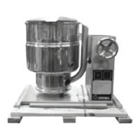
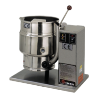
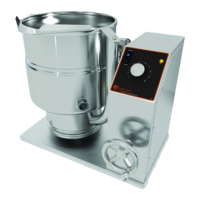
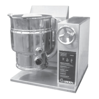
The Groen Kettle is provided with complete
internal wiring. It is ready for
immediate connection. A wiring
diagram is provided in this
manual and on the inside of the
control housing service panel.
Any mechanical or electrical
changes must be approved in by
Groen’s Food Service Engineering Department.
WARNING
INSTALLATION OF THE KETTLE MUST BE
DONE BY A CERTIFIED ELECTRICIAN OR
GROEN AUTHORIZED REPRESENTATIVE
QUALIFIED TO WORK WITH ELECTRICITY.
IMPROPER INSTALLATION CAN RESULT
IN INJURY TO PERSONNEL AND/OR
DAMAGE TO EQUIPMENT.
The completed unit has been operated at the
fa
ctory to test all controls and heater elements.
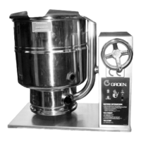
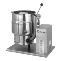
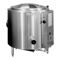
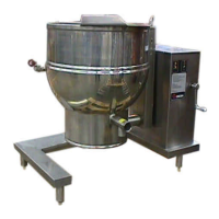
1. Set the kettle in place and level it. The
base should be securely fastened to a
table or work surface. Four 3/8”-16 N.C.
threaded couplings are provided in the
base of unit. Installation under a ventilation
hood is recommended.
2. Once the unit is anchored to a mounting
surface, apply a small bead of silicone
caulk around the perimeter of the kettle
base and seal the joint.
3. Provide electrical power as specified on
the electrical information plate attached to
the equipment. Observe local codes
and/or The National Electrical Code in
accordance with ANSI/NFPA 70 - (current
edition).
4. Standard equip
ment is shipped ready for
208V, 3-phase or 480V, 3-phase
operation. Refer to the wiring diagram
located on the inside cover of the control
box and the instructions below for
conversion to single-phase operation. A
jumper wire and “conversion” label are
included with the unit. They can be found
in a plastic bag attached to the trunnion
assembly inside the control box.
CAUTION
BEFORE ANY ELECTRICAL CONVERSION,
VERIFY THAT THE BRANCH CIRCUIT
WIRING IS ADEQUATE TO HANDLE ANY
INCREASE AMPERAGE REQUIREMENTS.
REFER TO THE ELECTRICAL
SPECIFICATIONS LISTED BELOW.
a. For conversion from 208V, 3-phase to
208V or 240V 1-phase O
R 480V,
3-phase to 480V, 1-phase:
i. Verify that the branch circuit wiring is
adequate for any increased
amperage requirements (see table
on page 8).
ii. For 240V 1-phase only, enlarge
electrical inlet opening for 1" conduit
fitting. Use a 1" sealtite conduit
fitting.
iii. Refer to wiring diagram for field
conversion.
iv. For 240V 1-phase only
, pull lead
from 208V tab on control
transformer and insert on 240V tab
(See Photo #1).
v. Complete “conversion label”
(supplied in bag) and adhere it to the
control box near the UL dataplate.
b. For conversion from 208V, 3-phase to
240V, 3-phase:
i. Verify that the branch circuit wiring is
adequate for any increased
amperage requirements (see table
on page 8).
ii. Pull lead from 208V tab on control
transformer and insert on 240V tab.
(See Photo #1)
iii. Complete “conversion label”
(supplied in bag and adhere it to the
control box near the UL dataplate).