EasyManua.ls Logo

Groeneveld AC3 - User Manual

Groeneveld AC3
20 pages
Print Icon
To Next Page IconTo Next Page
Loading...
GROENEVELD—NORTH AMERICA
AC3InstallaonManual
GVNA_IM003.1_JFAC3OperaonandMaintenance
AC3 Pump Info
MaximumWorkingPressure:1740psi(120bar,12MPa)
Maximumoperangtemperature:122°F/50°C
*(Notethatoperangoverthemaximumtemperaturewilleffectlifeofthepump)*
Minimumoperangtemperature:40°F/‐40°C(withSAE80/90Oil),5°F/‐15°C(withgrade2grease).
IPRang:IP66
Voltage:12Vor24V
PowerRang:2A
FuseRang:2A
MaxLineLengthperInjector:50(15m)
ThisprintandtheideasandprinciplesrepresentedontheprintarethepropertyofGroeneveldLubricaonSoluons.Thisprintisnottobecopiedorreproduced(evenextracts)
withoutpriorwrienconsentofGroeneveld.Everycarehasbeentakentoensuretheaccuracyoftheinformaoncontainedinthispublicaonbutnoliabilitycanbeacceptedfor
anylossordamagewhetherdirect,indirectorconsequenalarisingoutoftheuseoftheinformaoncontainedherein.
Question and Answer IconNeed help?

Do you have a question about the Groeneveld AC3 and is the answer not in the manual?

Overview

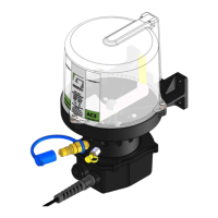
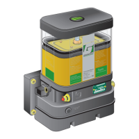
The Groeneveld AC3 is a multi-line lubrication system designed for automatic lubrication of machinery, primarily in vehicle applications, to enhance reliability and performance. It is intended for professional installation and use.

Function Description:

The AC3 pump system delivers lubricant to various bearing points on a machine. It operates automatically when the vehicle ignition is switched on, ensuring consistent lubrication. A built-in memory on the pump's printed circuit board prevents over-lubrication during short trips or multi-drop operations by retaining its position within the delay cycle if power is interrupted. The system can be programmed for continuous operation or with various delay times, allowing for customized lubrication intervals based on application needs. Lubricant is distributed through semi-rigid nylon tubing, which can be grouped into "looms" for organized routing to the bearing points. The system is designed to prevent air entrapment and cavitation during refilling, especially when using the standard grease nipple adaptor.

Important Technical Specifications:

  • Maximum Working Pressure: 1740 psi (120 bar, 12 MPa)
  • Operating Temperature Range:
    • Maximum: 122°F (50°C) (Note: Operating over this temperature will affect pump life).
    • Minimum: -40°F (-40°C) with SAE 80/90 Oil; 5°F (-15°C) with grade 2 grease.
  • IP Rating: IP66
  • Voltage: 12V or 24V
  • Power Rating: 2A
  • Fuse Rating: 2A
  • Max Line Length per Injector: 50ft (15m)
  • Reservoir Capacity: 3 liters (for AC3 models)
  • Pumping Unit Output/Stroke: Varies by unit, from 0.010 cc (Red) to 0.100 cc (Black).
  • Output Pressure from each Pumping Unit: 1740 PSI / 120 Bar
  • Recommended Lubricants: NLGI Grade 000, 00, 0, 1, and 2 grease, FG3,0 fluid grease, and oils with a minimum viscosity of SAE80. Bentone/bentonite, molybdenum, and graphite-containing greases, as well as heavy tackified greases, should not be used.
  • Pump Cycle Times and Programming: Configurable via a rotary switch on the PCB, offering continuous operation at 1.8 rpm or 0.9 rpm, or delay times ranging from 3 minutes to 36 minutes. Each cycle involves the pump running for 1 minute and 8 seconds after the delay period.
  • Mounting Dimensions:
    • AC3 pump clearance: 175mm (height) x 115mm (width).
    • Minimum clearance for 1 row/12 outputs: 280mm (height). Additional 10mm per row up to 7 rows max.
    • Clearance at base for manual override button: 212mm (pump body) / 265mm (overall, allowing for looming).
    • Mounting Centres: 119mm x 45mm, with four Ø6.5mm fixing holes.

Usage Features:

  • Automatic Lubrication: Connects directly to the vehicle ignition system for automatic operation when the ignition is on.
  • Programmable Delay Times: Users can adjust the lubrication frequency using a rotary switch on the internal PCB, choosing from continuous operation or various delay intervals (3, 7, 11, 15, 19, 24, 30, or 36 minutes).
  • Manual Override Button: Located at the base of the pump, this button allows for manual activation of a lubrication cycle (1 minute and 8 seconds run time) for testing or immediate lubrication.
  • Indication Lamp: Integrated into the manual override button, it lights up for continuous power supply and flashes slowly when the motor is in operation.
  • Looming System: Lubrication lines can be grouped and protected with conduit, spiral binding, sleeving, or tape for organized and secure routing.
  • Refill Procedure: Designed to prevent air entrapment, using a grease nipple adaptor for most grease types up to NGLI Grade 2. Bulk fill adaptors are also available.
  • Part Number Identification: A clear system for identifying pump variants based on reservoir size, timer setting, voltage, manifold size, and fill type (Zerk or Quick/Bulk Fill).

Maintenance Features:

  • System Operation and Testing: Regular inspection of lubrication points for fresh grease, checking fittings and connections, and verifying lubrication lines for breaks or wear.
  • Reservoir Replacement: Simple procedure involving removing three screws, the old O-ring, positioning a new O-ring and reservoir, and re-tightening screws to 3Nm (2.2lbf.ft).
  • Paddle Replacement: Involves removing the reservoir, then using a 17mm wrench to remove the retaining nut and washer, lifting the paddle blade, positioning a new paddle, and re-tightening to 7Nm (5.16lbf.ft).
  • Motor Replacement: Requires removing the motor cover, disconnecting the Molex connector, loosening two screws on the retaining plate, replacing the motor, and reassembling with a new O-ring, torquing screws to 1.5Nm (1.1lbf.ft) and 0.3Nm (0.22lbf.ft) for the cover.
  • PCB Replacement: Involves accessing the PCB, disconnecting power and manual override cables, replacing the PCB, setting the rotary switch to the desired setting, and reconnecting all wires.
  • Troubleshooting Chart: Comprehensive charts are provided for both lubrication and electrical issues, offering common problems, causes, and solutions (e.g., empty reservoir, defective pumping unit, high pressure, bad wiring).
  • Refill Period Calculation: A formula is provided to calculate typical refill periods based on the number of pumping units, output quantities, and programmed delay times, ensuring the pump and bearing points do not run dry.
  • Spare Parts Availability: A detailed list of spare parts, including pumping units, manifolds, motors, and various connectors, is provided for easy ordering and maintenance.

Groeneveld AC3 Specifications

General IconGeneral
BrandGroeneveld
ModelAC3
CategoryWater Pump
LanguageEnglish

Related product manuals