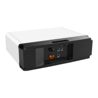
The GROWATT Future-H Series Energy Storage System is an ALL-IN-ONE solution designed for efficient energy management. This comprehensive system integrates an inverter (SIM 6000 ES Plus-H series), lithium batteries (ABM 5.5L-A1-H series), and a mounting base (ABM Battery Base), offering a versatile and scalable approach to energy storage. The system is engineered to support various combinations of inverters and batteries, providing flexibility to meet diverse energy demands. It boasts a robust design capable of supporting a maximum load of 400Kg, ensuring stability and durability.
Function Description
The primary function of the Future-H Series Energy Storage System is to store electrical energy, typically generated from renewable sources like solar panels, and then supply this energy as needed. The integrated inverter converts direct current (DC) from the batteries into alternating current (AC) for household or grid use, and vice versa for charging. The system supports both single-phase and three-phase configurations, allowing for integration into various electrical setups.
The system's modular design allows for flexible scaling of both power output and energy capacity. For instance, a single inverter can be combined with 2 to 6 battery modules, offering energy capacities ranging from 11KWH to 33KWH and a rated output power of 6KVA/6KW. For higher power requirements, multiple inverters can be paralleled. Two inverters in parallel can achieve a rated output power of 12KVA/12KW with 4 to 6 battery modules, providing 22KWH to 33KWH of energy. For even greater power, three inverters can be paralleled, supporting both 1-phase and 3-phase configurations with a rated output power of 18KVA/18KW and 6 battery modules, delivering 33KWH of energy. This scalability ensures that the system can be tailored to specific energy consumption patterns and future expansion needs.
The system's operation involves charging the lithium batteries when excess energy is available and discharging them to power loads when generation is insufficient or during peak demand periods. This intelligent energy management helps optimize self-consumption, reduce reliance on the grid, and provide backup power during outages.
Usage Features
The Future-H Series system is designed for ease of installation and operation, though certain aspects require qualified personnel. The installation process begins with unpacking and inspecting the components for any damage. The system includes all necessary cables and connectors, such as communication cables, current sharing cables, parallel communication cables, MC4 connectors, copper connectors, tubular terminals, and R-type terminals, along with a user manual.
Installation Requirements:
- Location: The system should be installed in a smooth, solid location, at least 10cm away from any walls to ensure proper ventilation. It must not be installed in areas with flammable or explosive materials, or in areas prone to salt damage (within 500m of the shore or affected by sea breezes) to prevent corrosion and fire hazards. The installation site should also be inaccessible to children.
- Space: Adequate space must be left around the energy storage unit for installation and heat dissipation. Specifically, a minimum of 300mm clearance is required on the sides and top, and 300-600mm in front.
- Weight Considerations: When handling the device, appropriate precautions must be taken due to its weight. The manual provides weight categories (<18Kg, 18Kg~32Kg, 32Kg~55Kg, >55Kg) to guide safe handling. Protective gloves are recommended when handling the device by hand to prevent injury.
- Module Placement: The battery modules should be placed first, followed by the PCS (Power Conversion System) module, which must always be installed at the top. The modules should be installed vertically and not tilted. Fixing plates can be used for added stability if needed.
Electrical Connection:
- Safety First: Before any electrical connections, ensure the battery is turned off and verified with a meter.
- Grounding: Each battery module and inverter must be properly grounded. Copper connectors are used for grounding, secured with M6 screws to achieve a torque value of 1.2-1.6 Nm. The recommended wire gauge for grounding is 10AWG*20cm.
- Power Connections: Power copper connectors are used for inter-module connections, secured with M6 screws at a torque value of 2-3 Nm. The current capacity of these connectors is 250A. For systems with three inverters in parallel, additional power cables (prepared by the user) are required due to higher current demands. The recommended wire size for these additional cables is 2AWG, with a length of <530mm, and ring terminals with a D(mm) of 6.4 and L(mm) of 39.2.
- Communication: Communication cables are essential for the coordinated operation of the system. The manual details connection diagrams for one, two, and three inverters in parallel, including current sharing, RS485, and DO/DI connections. A shorting cap is used in specific configurations.
- Battery Address Setting: Lithium battery module address settings are crucial for proper communication and operation. Users are directed to the ABM 5.5L-A1-H user manual for detailed instructions on this process.
- External Electrical Connection: For external electrical connections of the energy storage system, users should refer to the SIM 6000 ES Plus-H user manual for comprehensive guidance.
Power On/Off Procedure:
- Power On:
- Verify all cables are correctly connected.
- Press the power button of any battery module for more than 1 second; the RUN/ALM and SOC lights should turn on.
- Wait approximately 5 seconds.
- Press the inverter ON/OFF button to start the inverter.
- Power Off:
- First, turn off any electrical devices connected to the inverter's load end.
- Press the inverter on/off button to turn off the inverter.
- Press the power button of any battery module for 3 seconds and then release; the battery will enter shutdown state, and all LED lights will turn off.
Maintenance Features
Routine maintenance is vital for ensuring the long-term and optimal operation of the Future-H Series Energy Storage System. Adhering to the recommended maintenance schedule helps prevent issues and prolong the system's lifespan.
System Power-Off for Maintenance:
- Safety Precaution: After the system is powered off, residual power and heat may still be present, posing risks of electric shocks or burns. Therefore, protective gloves must be worn, and operations should only commence at least 5 minutes after the system is powered off, ensuring all indicator lights are off.
- Complete Shutdown: When the system is running, simply turning off the inverter switch does not completely power down the system. For maintenance operations, the battery switch must also be turned off. The detailed power-off steps are provided in the "Power off" section.
Routine Maintenance Schedule:
- System Cleanliness (for inverter):
- Method: Clean the dust on the dust sponge.
- Interval: Once every 3 months.
- Electrical Connection:
- Method:
- Check if any cable connection is off or loose.
- Check if any cable is damaged, especially for cuts on the sheath where the cable contacts metal surfaces.
- Interval: Half a year after initial debugging and testing, then once every six months to one year thereafter.
- Grounding Reliability:
- Method: Check if the grounding cable is reliably grounded.
- Interval: Half a year after initial debugging and testing, then once every six months to one year thereafter.
For troubleshooting specific issues, users are advised to consult the SIM 6000 ES Plus-H user manual or the ABM 5.5L-A1-H user manual, which provide detailed guidance on diagnosing and resolving problems. This structured approach to maintenance ensures the system remains in optimal working condition, maximizing its efficiency and reliability over time.