3 Electrical Connection
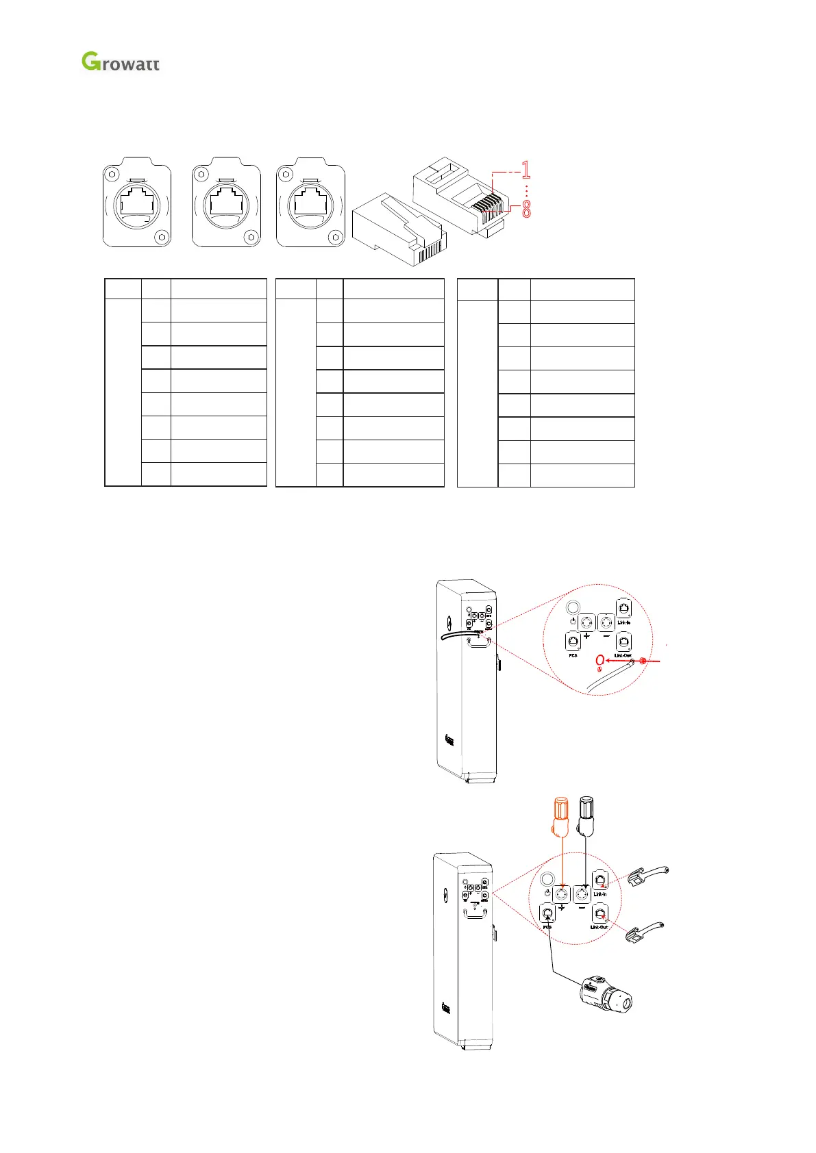
Communication interface definition:
1
8
5
PCS
Link-In
Link-Out
Item No. Denition
PCS 1 PCS-RS485-B
2 PCS-RS485-A
3 GND-ISO
4 PCS=CANH
5 PCS=CANL
6 GND-ISO
7 PCS-WAKE-
8 PCS-WAKE+
Item No. Denition
Link-
In
1 COM-CANH
2 COM-CANL
3 Encode-IN+
4 GND-ISO
5 Master-Select
6 GND-ISO
7 GND-ISO
8 WKP-OUT+
Item No. Denition
Link-
Out
1 COM-CANH
2 COM-CANL
3 Encode-OUT+
4 GND-ISO
5 Slave-Last
6 GND-ISO
7 GND-ISO
8 WKP-OUT+
3.1 Connect Cables for Single Battery
1. Measure battery voltage with a multi-meter
and ensure the voltage output is 0V under power off mode.
2. Fasten grounding terminal and grounding cable
with M6 screw (recommending a torque of
5N.m).
3. Insert power cables into DC Breaker and battery
terminals (orange positive cable and black
negative cable);
Plug one end of Network Cable A into
battery port (lablling as PCS)
and the other end into PCS.
to PCS Network Plug
Plug 1
to DC Breaker
Positive Terminal
to DC Breaker
Positive Terminal
Plug 2
.
.
Shenzhen Growatt New Energy Technology CO.,LTD
 Loading...