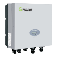
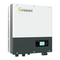
NEO 600-1000M-X Microinverter
Quick installation Guide (LoRa)
1.
Overview
1.This document is intended for use as a quick installation guide. For details, please refer to the Installation and Operation Manual.
2.Growatt shall not be liable for any damage caused by improper operations.
Note:
2.
Installation
1.1 Microinverter Overview
1.2 System Overview
1.3 Accessories
a. Mount the NEO Microinverter to the rail using the mounting screws recommended by
your module racking vendor.
b. Maintain a minimum of 20 mm clearance between the roof and the back plate of the
Microinverter to ensure ventilation and heat dissipation. Do not install the
Microinverter at the gap between the PV modules.
Step 1 Install the NEO Microinverter
1. AC connection
Method 1: Connect the Microinverter to the grid with the AC bus cable. (You can skip Steps a and b);
Method 2: Assemble the AC trunk connector and the AC cable to create the AC bus cable, then connect the Microinverter to the grid with the
assembled cable.
Application Scenario 1: Multi-Microinverter system (rooftop solar)
Step 3 Electrical Installation
F
G
H
A
C
B
D
E
Application Scenario 1: Multi-Microinverter system
(rooftop solar)
Application scenario 2: Single-Microinverter system
(balcony solar)
Datalogger
WiFi Router
ShineServer Web
ShinePhone APP
Solar Panel
Micro Inverter
Power Grid
Cloud Server
1. Up to five microinverters can be connected to the ShineWeLink.
2. Position the ShineWeLink next to the router, but maintain a minimum distance of 0.5m to avoid distortion resulting from the
excessively strong signal.
3. Do not place the inverter, the router and the ShineWeLink on the same vertical line to avoid affecting the signal strength.
Note:
Packing list
Please select the appropriate
accessories and tools based on the on-
site conditions.
Note:
Microinverter
Quick Installation
Guide & Warranty
Card
Application Scenario 1: Multi-Microinverter system (rooftop solar)
Mounting
screw (M6/M8)
Grounding
screw (M4)
PV Extension
Cable
PV Terminal
Dust Plug
PV Connector
Unlock Tool
AC Sub Connector
Removal Tool
AC Trunk Connector
Unlock Tool
AC Trunk
End Cap
AC Trunk
Port Cap
AC Trunk
Connector
AC Cable
(AWG 12/10)
Application Scenario 2: Single-Microinverter system (balcony solar)
Male AC Sub
Connector
or
M6/M8
128mm
1
2
Mounting Torque 9N·M
b. In area with special grounding
requirements, external
grounding may be needed by
grounding the screw hole on the
handle.
a. The AC drop cable has an
embedded earth wire, which
might be sufficient to ensure
proper grounding.
Step 2 Ground the system
a. Prepare the AC trunk connector.
Disassemble the connector as the
figure shows.
b Crimp an EN6010 non-insulated cold-pressed terminal with each cable using a hexagonal .
wire crimper. Thread the cables through the cover and sealing plug. Connect the L, N and PE
cables to the corresponding slots, and then tighten all screws. Re-install the upper cover,
ensuring that you hear a “click” sound.
Ÿ Please insert the AC trunk end cap to the connector at the end of the AC bus cable to avoid water or dust penetration.
Ÿ Please plug the AC trunk port cap in any vacant AC trunk port to prevent it from water and dust.
Connect the AC drop cable to the AC trunk connector. Make sure to hear the "click" sound as proof of a robust connection.
c Attach the AC bus cable to the mounting rack and secure the AC trunk connector..
Connect the AC bus cable to the distribution box, and wire it to the local grid network.
E6010
10±1mm
40±3mm
N(Black)
PE(Green&Yellow)
L(Red)
Click
Click
Click
1
2
1
2
Click
Click
Max. number of Microinverters
Recommended number of Microinverters
on the AC bus cable:
Mounting
screw (M6/M8)
Grounding
screw (M4)
PV Extension
Cable
PV Terminal
Dust Plug
PV Connector
Unlock Tool
AC Sub Connector
Removal Tool
b. Connect the DC cables of PV modules to the DC input of the Microinverter.
a. Mount the PV modules above the Microinverter.
2. Connect the PV modules
Datalogger
WiFi Router
ShineServer Web
ShinePhone APP
Cloud Server
Solar Panel
Micro Inverter
Distribution Panel
AC Breaker
or
AC Bus Cable
(AWG 12/10)
AC Adapter
Cable(EU)
AC Cable
(AWG 16/14)