6
English (US)
5.4.1 For line cord models
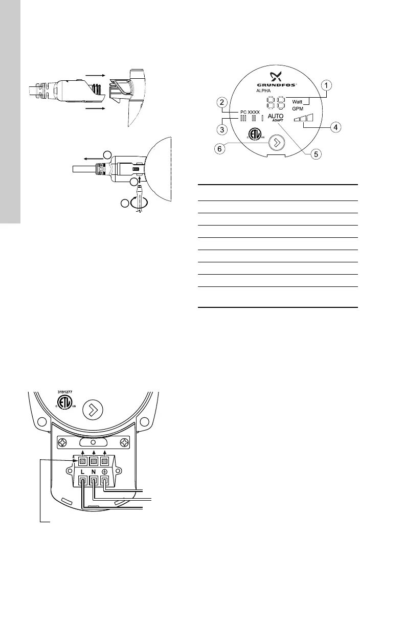
Follow procedure outlined in fig. 5.
Fig. 5 Connecting and removing power
plug for line cord models
5.4.2 Terminal box models
Wiring procedure:
1. Loosen terminal box screw from terminal box
cover.
2. Utilize either conduit port for wiring entrance.
3. Gently push open wiring terminal levers
(L-N-G) for wiring installation.
4. Slide terminal box cover over terminal box
body.
5. Tighten terminal box screw Phillips #1
(5 in-lbs).
6. Apply power.
7. Lights on the control panel indicate electrical
supply has been switched on.
Fig. 6 Terminal box wiring, 1 x 115 V
6. Operation
6.1 Control display
Fig. 7 Control display
TM04 3420 1010TM04 7035 1410
To remove cord plug from pump
(bottom view):
Insert line cord plug onto pump
(side view):
1. Insert 1/8 in. flat blade
screwdriver into slot.
2. Rotate screwdriver.
3. Pull cord to remove.
White
Black
Green
Wiring terminal levers
TM04 3421 3511
Pos. Description
1 LED showing Watt or flow indicator
2 Production code:
• 1st and 2nd figures = year
• 3rd and 4th figures = week
3 LED indicating fixed speed
4 LED indicating constant pressure
5 LED AUTO
ADAPT
6
Push-button for selection of pump
setting
 Loading...