6
3.1 Terminal box positions
The terminal box can be turned to the positions
shown in
o.
3.2 Changing the terminal box position
Change the terminal box position as shown in
p.
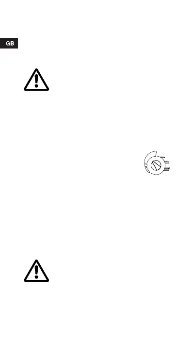
3.3 Bypass valve
3.4 Non-return valve
If a non-return valve is fitted in the pipe system,
see
q, it must be ensured that the minimum
pump pressure is always higher than the clos-
ing pressure of the valve.
3.5 Air separator pump
4. Electrical connection
The electrical connection and protection should
be carried out in accordance with local regula-
tions.
Before the screws are removed, the
system must be drained or the isolat-
ing valves on either side of the pump
must be closed as the pumped liquid
may be scalding hot and under high
pressure.
If the pump is installed in a two-pipe
system with a bypass valve between
flow pipe and return pipe, it is recom-
mended to set the pump to constant
pressure control as illustrated in the
figure.
GRUNDFOS ALPHA+ pumps type A
must be fitted with an automatic air
vent. This must be fitted to the pump
housing before priming.