Coupling
Bolt Size
Min. Torque
Specifications
M6 . . . . . . . . . . . 10 ft-lbs.
M8 . . . . . . . . . . . 23 ft-lbs.
M10 . . . . . . . . . . 46 ft-lbs.
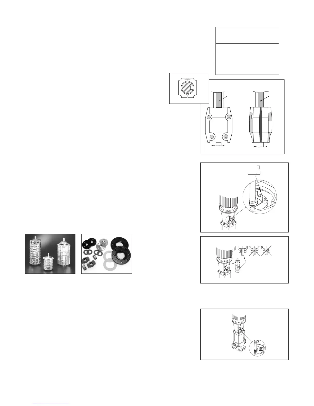
Figure 7
CR(N) 32, 45, 64, 90
NOTE: To avoid damaging the coupling halves,
ensure that no portion of the keyway on the
motor shaft lies within the gap between the
two coupling halves.
Figure 8
CR(N) 32, 45, 64 & CR90:
Place the plastic adjustment fork under the cartridge seal collar (see Figure 7).
Fit the coupling on the shaft so that the top of the pump shaft is flush with the bottom
of the clearance chamber in the coupling (see Figure 8).
Lubricate the coupling screws with an anti-seize and lubricating compound. Tighten the
coupling screws (finger tight) while keeping the coupling separation equal on both sides
and the motor shaft keyway centered in the coupling half as shown in Figure 6a. When
the screws are tight enough to keep the couplings in place, then
torque the screws evenly in a crisscross pattern.
Torque coupling screws to 62 ft.-lbs. Remove the adjustment fork
from under the cartridge seal collar and replace it to the storage
location (see Figure 9).
6. Check to see that the gaps between the coupling halves are equal.
Loosen and readjust, if necessary.
7. Be certain the pump shaft can be rotated by hand. If the shaft cannot be rotated or it
binds, disassemble and check for misalignment.
8. Prime the pump.
9. Follow the wiring diagram on the motor label for the correct motor wiring combina-
tion which matches your supply voltage. Once this has been confirmed, reconnect the
power supply wiring to the motor.
10. Check the direction of rotation, by bump-starting the motor. Rotation must be left to
right (counter-clockwise) when looking directly at the coupling.
11. Shut off the power, then re-install the coupling guards. After the coupling guards have
been installed the power can be turned back on.
Parts List
For each CR pump model Grundfos offers an extensive Parts List and diagram of part used in that
pump and is recommended to have on hand for future maintenance. In addition, the listings also
provide information about prepackaged Service Kits for those pump components most likely to
exhibit wear over time, as well as the complete Impeller Stack needed to replace the "guts" of
each model. These Parts Lists are available separately from the Grundfos literature warehouse or
as a set with extensive service instructions in the Grundfos CR Service Manuals (for a small
charge).
Spare Parts
Grundfos offers an extensive list of spare parts. For a current list of these parts, refer to: "All
Product Spare Parts/Service Kits" Price List, Form # L-SK-SL-002.
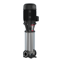
Left, prepackaged impeller stacks
ready for immediate installation;
right, prepackaged flange kits.
Figure 6a
All CR(I)(N)(X)(T)
Figure 9
 Loading...