TM031130
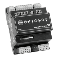
Mounting on DIN rail
Related information
9. Overview of inputs and outputs
14. Dimensions
4.5
EMC-correct installation
IO 351 is usually mounted in a panel also containing
a CU 351 and frequency converters, contactors and
other power equipment. In order to ensure a faultless
function, it is very important to install the electronic
modules in an EMC-correct way:
• Use screened cables for GENIbus. Connect the
screen to the cable clamp of the module forward
of the terminals AA, YY and BB.
TM031655
Screen fixed with cable clamp
Any isolating plastic tape between screen and sheath
must be removed before mounting the cable in the
cable clamp.
Signal conductors for digital and analog inputs and
outputs should be screened, i.e. run the screen all the
way to the IO 351 and connect it to frame with for
instance a cable clamp.
Alternatively, the signal conductors in the panel may
be unscreened if the panel is divided into a power
and a low-voltage area. Unscreened signal
conductors must not run in the power area, but
exclusively in ducts in the low-voltage area.
• Do not twist screen ends, as this will destroy the
screen effect at high frequencies. Use cable
clamps.
• The module construction ensures a good
electrical contact to the DIN rail. The DIN rail must
therefore have a good connection to functional
earth. If the module is mounted without a DIN rail
by means of the four mounting holes (pos. 6),
there must be a connection to functional earth
through the fitting (pos. 3). See fig. IO 351 A or IO
351 B.
• Use toothed washers and galvanically conducting
mounting plates.
Related information
2. General description
4.6 Allocation of address
Address
1. pump module 31
2. pump module 32
1. input-output module 41
2. input-output module 42
1. Point the R100 against the IO 351 and press [OK].
See fig. R100 and indicator lights.
2. Press [>] to go to the menu INSTALLATION.
3. Press [∨] to get to Number (address).
4. Set the address with [+] and [-].
5. Point the R100 against the IO 351 and press [OK].
9
English (GB)

 Loading...