TM072418
TM072419
TM072480
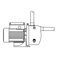
Fig. How to attach the lifting handle on the pump
3.2.3 Connecting the pipe system
Install the product so that it is not stressed by the pipe
system.
Pipe dimensions:
• The diameter of the inlet pipe must be larger than 1",
if the inlet pipe is longer than 10 m, or if the suction lift
exceeds 4 m.
• If a hose is used as inlet pipe, it must be non-
collapsible.
We recommend that you install isolating valves on both
the inlet and outlet side of the pump.
1. Seal the pipe fittings with thread sealing tape or similar.
2. Connect pipes to the inlet and outlet port on the pump. Do not
let the pump support the pipes.
Use a pipe wrench or similar tool.
3. Fit a foot valve to the inlet pipe if the pump is installed above
the liquid level, for example if you pump from a well, tank or
reservoir. We recommend a foot valve with strainer.
4. We recommend that you install a filter on the inlet side to
protect the pump from sand, gravel or other debris if the pump
is to be used for pumping rainwater or well water.
5. Make sure that the inlet pipe has a gradual upward slope of 5 °
towards the pump to avoid air pockets, especially under
suction-lift conditions.
TM064532
Fig.
Inlet pipe with gradual upward slope towards the pump
3.2.3.1 Maximum system pressure
Make sure that the system in which the pump is installed
is designed for the maximum pump pressure.
The maximum inlet pressure depends on the head at the actual
duty point. The sum of the inlet pressure and the head must not
exceed the maximum system pressure.
We recommend that you install a pressure-relief valve to protect the
pump so that the outlet pressure does not exceed the maximum
system pressure.
3.2.3.2 Inlet and outlet pipes
Please follow these general precautions when connecting the inlet
and outlet pipes.
Do not let the pump support the pipes. Use pipe hangers
or other supports at proper intervals to provide pipe
support near the pump.
The internal diameter of the pipes must never be smaller
than the diameter of the pump ports.
• Install the pipes so that air pockets are avoided, especially on
the inlet side of the pump.
• Use eccentric reducers with the tapered side down.
• Make sure the pipes are as straight as possible to avoid
unnecessary bends and fittings. We recommend long-radius 90
° pipe bends to decrease friction loss.
• Run the inlet pipe as direct as possible and, ideally, make sure
the length is at least ten times the pipe diameter.
• If possible, run a horizontal inlet line. We recommend a gradual
upward slope to pumps operating in suction-lift conditions, and
a gradual downward slope to pumps operating in positive inlet-
pressure conditions.
TM040338
Fig.
Recommended pipe installation to avoid friction and air
pockets
• A short pipe must be the same diameter as the inlet port or
larger.
• A long pipe must be one or two sizes larger than the inlet port,
depending on the length.
7
English (GB)
 Loading...