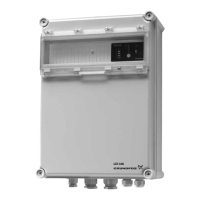
TM078169
Sensor connections
Terminal assignment
1 Supply voltage, pump (outlet)
2 Mains voltage (L)
3 Supply voltage, pump (charge)
4 Mains voltage (N)
5 Alarm contact (COM)
6 Alarm contact (NC)
7 Alarm contact (NO)
8
Sensor contact, long electrode (Earth,
green and yellow)
9
Sensor contact, short electrode (ON,
blue)
10
Sensor contact, middle-sized electrode
(OFF, brown)
11
Sensor contact, very short electrode
(ALARM, black)
2.2 Description of function
The voltage between the electrodes is approximately
12 VDC, and the operating voltage for the pump
connection is 1 x 230 V. The four electrode rods
extend into the liquid to be pumped at differing
lengths. The longest electrode functions as a frame
electrode; the second-longest is the stop electrode,
followed by the start electrode, the shortest electrode
being the alarm electrode.
The level controller is factory-set to emptying
function. If the liquid level rises to the start electrode,
the controller switches on the pump. If the liquid level
falls below the stop electrode, the controller switches
the pump off. If the liquid level reaches the alarm
electrode, a potential-free contact in the control box
closes, and the built-in buzzer will sound. The
additional potential-free changeover contact is
provided for special applications and can also be
used for an external alarm. The position of the
contacts (spring terminals) on the guide plate in the
control box is shown in fig. Terminal diagram.
The function can be reversed by moving the cable
from connector X1-1 to connector X1-2, so that the
connected device turns on when the stop electrode is
reached, and turns off when the start electrode is
reached (filling function). The alarm is then triggered
when the tank to be filled is overfilled.
After installation, the level controller functions
automatically. Settings on the device must not be
adjusted.
3. Receiving the product
The level controller is delivered in appropriate
packaging and should remain packed until
installation.
4. Installation requirements
DANGER
Electric shock
Death or serious personal injury
‐ If national legislation requires a
Residual Current Device (RCD) or
equivalent in the electrical installation,
this must be type B or better, due to
the nature of the constant DC leakage
current. The RCD must be marked with
the following symbols:
‐
TM072868TM072869
WARNING
Explosive environment
Death or serious personal injury
‐ Installation and operation in a
potentially explosive environment are
not allowed.
DANGER
Electric shock
Death or serious personal injury
‐ Switch off the power supply before you
start any work on the product.
‐ Make sure that the power supply
cannot be switched on accidentally.
‐ The electrical connections on the
control box must not be exposed to
moisture.
7
English (GB)
 Loading...
