English (GB)
15
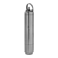
7.15 Configuring the controller
The terminal box is configured from factory for the intended
application and pump type. The configuration file number appears
from the terminal box configuration label which is placed inside
the terminal box. See fig. 32.
Fig. 32 Position of configuration label
If the terminal box, functional module or power module is
replaced or mounted on another motor, it must be reconfigured.
Use the PC Tool E-products for that purpose. To establish
connection to the motor, use the Grundfos GO Remote MI 301 or
PC Tool Link.
7.15.1 Connection to motor by means of Grundfos GO
Remote MI 301
Configuration can be done in three ways:
• Radio Scan
• Direct Connect
• IR Connect.
Equipment
• PC Tool E-products, version 14.00.00 or newer
• MI 301 (PN 98046408) with USB cable.
IR Connect
1. Switch on the power supply to the pump.
2. Connect MI 301 to the PC.
3. Start PC Tool. The first time the program is started, the
message "No COM port selected" will be shown. Click [OK].
Fig. 33 No COM port selected
4. Select "Preferences" in the main menu under "Files".
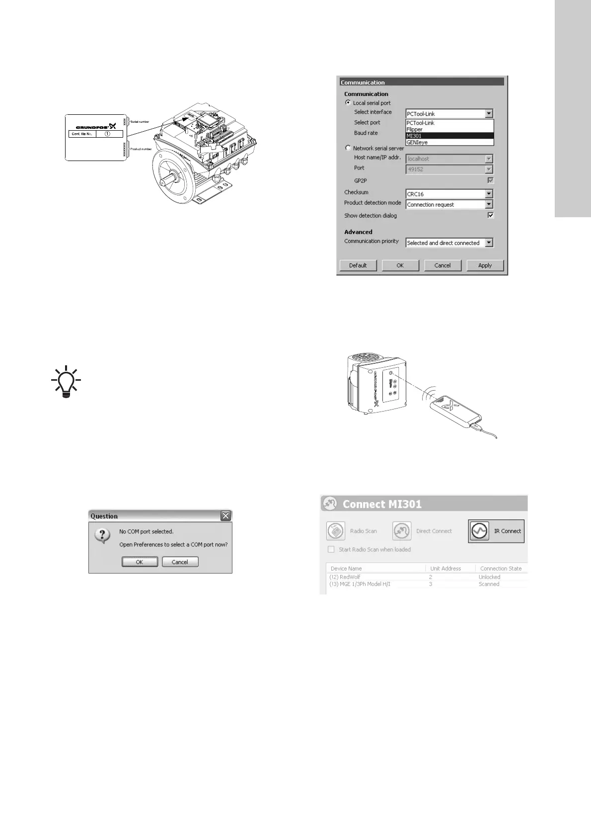
5. Open the dropdown menu "Select interface" and select "MI
301". See fig. 34.
Fig. 34 Selecting the user interface
6. Open the dropdown menu "Select port" and select the port
"PCTool-Link". See fig. 34. Click [Apply].
7. Point the MI 301 at the IR eye of the pump. The distance is
maximum 20 cm. See fig. 35.
Fig. 35 IR connection via MI 301
8. Click [IR Connect]. See fig. 36. Wait while connection to the
pump is established (10-20 seconds).
Fig. 36 IR Connect
9. To find the GSC file, see section 7.15.3 Configuration with the
PC Tool E-products.
TM05 5967 4212
If the power supply to the pump is interrupted during
configuration, the update will be lost.
This will, however, not damage the controller. Start
from the beginning.
TM05 6928 0313
TM05 7037 0413TM05 7132 0613TM05 6930 0313
 Loading...