28.04.2003
GB
7 / 24
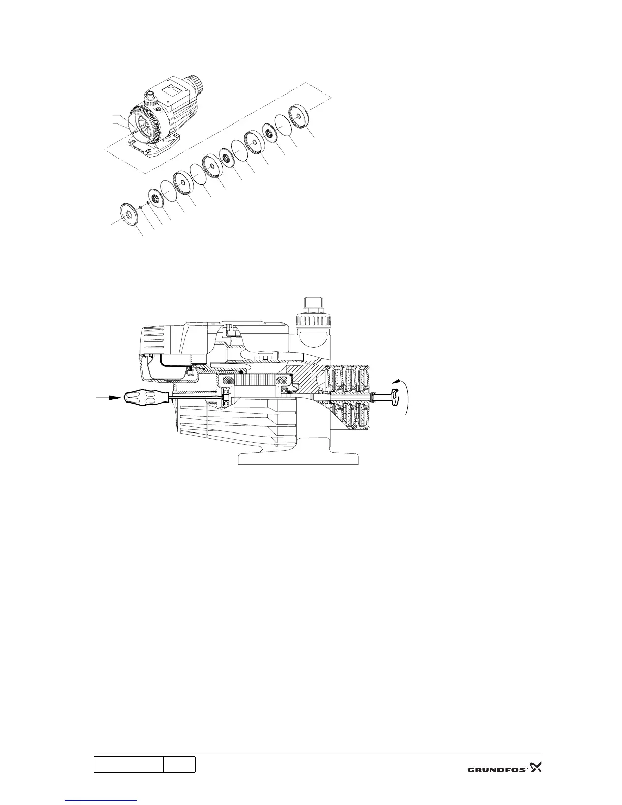
4. Fit the chambers pos. 4, O-rings pos. 37 and impellers pos. 49 on the motor unit/shaft pos. 150, see
drawing. Note: There is no O-ring on the chamber next to the intermediate part pos. 2.
5. Fit the washer pos. 66 and the nut pos. 67 and tighten it with 7 Nm. Hold the shaft end using a
screwdriver.
6. Fit the O-rings pos. 37 to the back of the inlet parts and fit the inlet parts to the chamber stack.
7. Fit the O-ring pos. 37b and lubricate it.
8. Fit the O-ring pos. 37a on the intermediate part pos. 2 and lubricate it.
9. Lubricate and fit the pump sleeve pos. 16. Check that the pin at the bottom of the intermediate part fits
the hole of the pump sleeve.
10. Push the pump sleeve into position and tighten the three screws pos. 91.
11. Fit and tighten the strap pos. 92.
TM02 6628 1203
TM02 6704 1403
4
37
49
4
37
49
4
37
49
37
49
66
67
6
150
2

 Loading...


