Page 7
Page 4
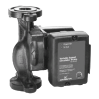
4. Pump Installation
Remove the control from the pump and install pump in
piping.
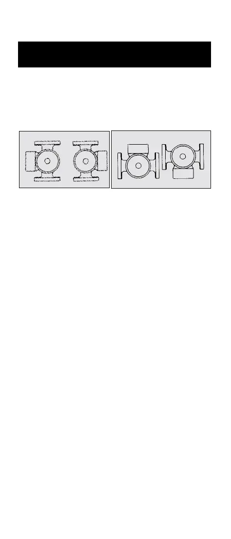
Position of terminal box:
Prefered installation of the pump will have the
terminal box located to one side of the pump or the
other, with the conduit entry down.
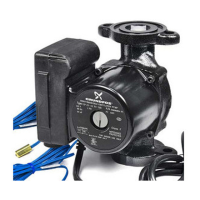
If the terminal box position needs to be changed, it is
best to do so before installation. However, if the pump
is already installed, ensure that the electrical supply is
turned off and close the isolation valves before
removing the Allen screws.
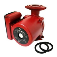
To Change terminal box position:
• Remove the four (4) Allen screws (4 or 5mm
wrench) while supporting the stator (motor).
• Carefully separate the stator from the pump
chamber and rotate it to the correct terminal box
orientation.
• Replace the Allen screws and tighten diagonally
and evenly (7 ft. –lb. torque).
• Check that the motor shaft turns freely. Remove
the large screw in the middle of the nameplate,
insert a small flat blade screwdriver into the end
of the shaft, and turn gently.
• If the shaft does not turn easily, repeat the
disassembly/reassembly process.
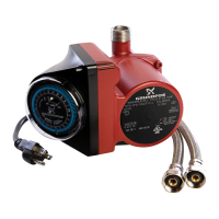
Pump Mounting: For Indoor Use Only
Arrows on the side or bottom of the pump chamber
indicate direction of flow through the pump. Grundfos
Variable Speed pumps can be installed in both vertical
and horizontal lines.
Figure 4A - Prefered Terminal
Box Orientation
Figure 4B - Optional Terminal Box
Orientation (see Operational Limits)
Setting Dip Switches
Figure 7A -
Dip Switches
⇑⇑
⇑⇑
⇑
Dip switch settings
POSITION
Feature Explanation
Dip switch C - minimum speed off/minimum speed
15%. When dip switch C is in the ON position the
variable speed of the pump will have a range from
minimum speed = off to maximum speed = 100%.
When dip switch C is in the OFF position the variable
speed of the pump will have a range from minimum
speed = 15% to a maximum speed = 100%.
Dip switch D - speed control external/speed control
maximum % dial. When dip switch D is in the ON
position an external V(dc)/mA signal will cause the
pump speed to vary and the dial on the terminal box
will function in the -5% to +5% mode. When dip switch
D is in the OFF position turning the manual % dial will
vary the pump speed. The pump will not respond to an
external V(dc)/mA signal even if one is present. The
terminal box and the dial will function in the minimum
to 100% mode.
7. Settings
ON
OFF DEFAULT
SWITCH
mA
(V) DC mA
0-10V
0-20mA
2-10V
4-20mA
min speed
15%
min speed
off
speed control
external
2-10V
4-20mA
min speed
off
speed control
manual % dial
speed control
external
A
B
C
D
ONON
ONON
ON
 Loading...