Do you have a question about the Grundfos UPM3 Auto 15/70 and is the answer not in the manual?
Details the different setting options available for the pump, including pressure and curve settings.
Provides the physical dimensions of the Grundfos UPM3 Auto 15/70 pump.
Explains electrical connection requirements, safety precautions, and fuse recommendations.
Presents performance curves showing pump head and flow rate relationships.
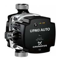
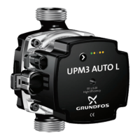
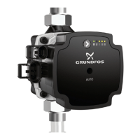
The Grundfos UPM3 Auto 15/70 is a compact, energy-saving, and high-performance pump designed specifically for the OEM market. It is utilized in various products due to its favorable characteristics.
The UPM3 Auto 15/70 pump is designed to circulate fluid in heating systems, particularly underfloor heating installations. It offers a range of operating modes and settings to adapt to different system requirements and optimize energy consumption. The pump's core function is to maintain a specified pressure or flow rate within the system, ensuring efficient heat distribution.
The pump features ten different setting options, categorized into three types of curves: Proportional Pressure, Constant Pressure, and Constant Curve. Each curve type offers distinct operational characteristics suitable for various system designs and demands. Proportional Pressure curves adjust the pump's head proportionally to the flow rate, which is often beneficial in systems with varying flow requirements. Constant Pressure curves maintain a consistent pressure difference across the pump, ideal for systems where a stable pressure is crucial. Constant Curve settings provide a fixed performance curve, suitable for applications with predictable flow and pressure needs.
The pump is equipped with an intuitive operating panel that displays the currently active setting. This allows users to quickly ascertain the pump's operational mode. The settings menu provides a comprehensive overview of all available options, with relevant settings highlighted for ease of identification.
Upon delivery, the Grundfos UPM3 Auto 15/70 is pre-set to Proportional Pressure, curve three. However, for underfloor heating installations, the manufacturer recommends manually changing this setting to Constant Pressure, selecting a curve that is adapted to the specific conditions of the installation. This adjustment is crucial for optimal performance and energy efficiency in underfloor heating systems.
Changing the pump setting is a straightforward process. Users can press the button on the pump to cycle through the available settings. Each press shifts the pump to the next setting in accordance with the settings menu. The desired setting can be selected by stopping at the appropriate option. The pump's display will indicate the currently active setting, allowing for easy verification.
The pump's electrical contact should be connected to a 230 V, 50 Hz socket by a qualified electrician. It is important to adhere to the provided wiring diagram for correct installation. The electrical contact no longer requires a 2-pole switch disconnector, simplifying the installation process. For safety, the electrical contact should be equipped with a slow-blow fuse of up to 10 A.
The Grundfos UPM3 Auto 15/70 includes several features to aid in maintenance and troubleshooting. The pump is equipped with an alarm code system that displays specific indications in the event of an operating problem. These alarm codes help users or technicians quickly diagnose issues.
For example, if the Red LED and Yellow LED #5 are illuminated, it indicates a "Blocked rotor" with an operation of "False start was 1.33 s." The recommended action for this is to "Wait or release rotor." If the Red LED and Yellow LED #4 are on, it signifies "Too low voltage," indicating "Only one warning, the pump operates as normal." In this case, the action is to "Check the voltage to the pump." If the Red LED and Yellow LED #3 are lit, it points to an "Electric fault," meaning the "Pump stops because of low voltage or serious fault." The suggested actions are to "Check voltage to pump / Replace pump/ impeller."
In cases of a blocked impeller, a specific maintenance procedure is outlined: "Release impeller using screwdriver PH2. Break the voltage to the pump. Insert the screwdriver into the center hole of the drive side, press the screwdriver in about 5 mm, then rotate forward/backward until the impeller loosens." This detailed instruction allows for effective resolution of a common pump issue.
Before performing any maintenance work on the pump, it is imperative to disconnect it from the mains power supply to ensure safety. This precaution prevents electrical shock and other hazards during servicing. The pump's design, including its compact dimensions and robust construction, contributes to its overall reliability and ease of maintenance.
| Max Head | 7 m |
|---|---|
| Power Input | 3-45 W |
| Voltage | 230 V |
| Frequency | 50/60 Hz |
| Type | Circulator pump |
| Maximum Operating Pressure | 10 bar |
| Port-to-Port Length | 130 mm |
| Insulation Class | F |
| Liquid Temperature Range | 2..95 °C |