English (GB)
8
2.5 Principle function of the components
Fig. 12 Components of a chlorinator
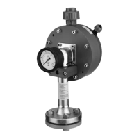
2.5.1 Vacuum regulator
• Reduces the gas pressure (overpressure) to subatmospheric
pressure (vacuum)
2.5.2 Measuring tube
• Displays the gas flow
2.5.3 Rate valve
• For adjustment of the required gas flow
– manually or automatically
2.5.4 Differential pressure regulator (Option: VGA-117)
• Regulates the difference of the pressures before and after the
rate valve to a constant value
– Adjusted dosing flow stays constant even when the injector
vacuum varies.
2.5.5 Vacuummeter (Option: VGA-117)
– Displays the injector vacuum
2.5.6 Injector
– Creates the vacuum necessary for operating the pant
– Mixes the chlorine gas with the water
TM04 0705 0908
Motive water
Vacuum regulator
Measuring
tube
Gas Dosing System
Differential
pressure
regulator
Vaccum
meter
Injector
Rate Valve
Chlorine gas

 Loading...