EasyManua.ls Logo

Grundig 26 GLX 3000 T User Manual

Grundig 26 GLX 3000 T
82 pages
To Next Page IconTo Next Page
Page #1 background imageLoading...
Page #1 background image
TV Service Manual
Zusätzlich erforderliche Unterlagen für den Komplettservice
Additionally required Service Documents for the Complete Service
Service
Manual
Materialnummer / Part Number 720100547000
Änderungen vorbehalten / Subject to alteration
TCC 1110 MP • Prepared in Germany
http://www.grundig.com
Sicherheit
Safety
Materialnr./Part No.
720108000001
Chassis T8
Toronto
32-7931a T GBH3133
Vision 3
26-3931 T GBH8426
32-3931 T GBH8432
Vision 4
26-4905 T GBH7326
26-4931 T GBH7126
32-4905 T GBH7332
32-4931 T GBH7132
Vision 6
26-6930 T GBH5726
32-6930 T GBH5732, GBH5733
Vision 9
26-9930 T GBH5926
32-9930 T GBH5932
Chassis T9
26 GLX 3000 T GBI1126
Question and Answer IconNeed help?

Do you have a question about the Grundig 26 GLX 3000 T and is the answer not in the manual?

Grundig 26 GLX 3000 T Specifications

General IconGeneral
BrandGrundig
Model26 GLX 3000 T
CategoryTV
LanguageEnglish

Summary

Allgemeiner Teil / General Section

Allgemeine Hinweise / General Notes

Essential safety, wiring, and measurement precautions.

Technische Daten / Technical Data

Comprehensive technical specifications for various chassis and models.

Service- und Sonderfunktionen / Service and Special Functions

Accessing and using service mode and special features.

Platinenabbildungen und Schaltpläne / Layout of the PCBs and Circuit Diagrams

Chassis Board T8 YVR190R-4, YVR190R-7

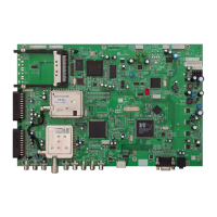
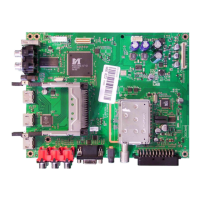
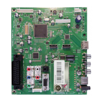
PCB layout and component placement for Chassis T8 models.

Chassis Board T9 YVR190R-8

PCB layout and component placement for Chassis T9 models.

Technische Daten / Technical Data

DISPLAY Specifications

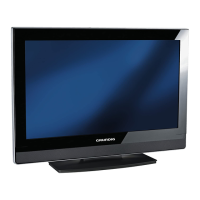
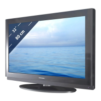
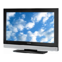
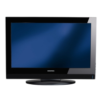
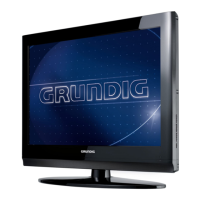
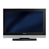
Technical details of the screen panel and image quality.

PC MONITOR MODE

Connecting a PC

Steps to connect a PC using VGA and audio cables.

Service- und Sonderfunktionen / Service and Special Functions

Service Mode Activation

Procedure to enter the service mode using a specific code.

Basic Settings in Service Mode

Table detailing essential settings configurable within the service mode.

Chassis Board T8 – Power Supply

Chassis Board T8 – Amplifier

Chassis Board T9 – Power Supply

Chassis Board T9 – Amplifier

Related product manuals