Do you have a question about the Grundig Vision 6 26-6831 T and is the answer not in the manual?
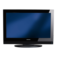
| Screen Size | 26 inches |
|---|---|
| Resolution | 1366 x 768 |
| Display Type | LCD |
| HD Type | HD Ready |
| HDMI Ports | 2 |
| USB Ports | 1 |
| Refresh Rate | 50 Hz |
| Aspect Ratio | 16:9 |
| Number of Speakers | 2 |
| VGA Port | Yes |
| Headphone Jack | Yes |
| Standby Power Consumption | 0.5W |
| Built-in Tuner | DVB-T, DVB-C |
Safety, wiring, and measurement guidelines for service operations.
Details on different chassis and software versions based on available displays.
Comprehensive specifications for various TV models and features.
Basic user operation and remote control functions.
Accessing service mode and special TV functions.
Schematic diagram for the power supply unit and its components.
Schematic diagrams for various audio and video input connectors.
Schematic diagram for the onboard tuner module.
Schematic diagram for the COFDM demodulator circuitry.
Schematic diagram for the scaler IC and its connections.
Schematic diagram for the Sub-MCU and its peripheral connections.
Schematic diagram for the PCMCIA interface and connector.
Schematic diagram for the audio amplifier circuit and components.
Component layout and placement for the YCR190R-3 chassis board.
Component layout and placement for the YCR190R-4 chassis board.
Main power supply board schematic and component connections.
Schematics and layouts for various keyboard models.
Schematics and layouts for IR/LED boards.