EasyManua.ls Logo

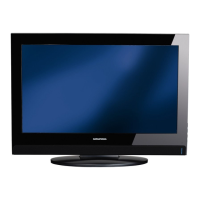
Grundig Vision 6 32-6831 T User Manual

Grundig Vision 6 32-6831 T
64 pages
To Next Page IconTo Next Page
Page #1 background imageLoading...
Page #1 background image
TV Service Manual
Zusätzlich erforderliche Unterlagen für den Komplettservice
Additionally required Service Documents for the Complete Service
Service
Manual
Materialnummer / Part Number 720100538000
Änderungen vorbehalten / Subject to alteration
TCC 1108 HH • Prepared in Germany
http://www.grundig.com
Chassis SE
Toronto
26-7831 T GBH3126
Vision 6
42-6831 T GBH1342
37-6831 T GBH1337
32-6831 T GBH1332
32-6832 T ECO GBH1232
26-6831 T GBH1326
26-6832 T ECO GBH1226
26-6832 F T ECO GBH1227
Vision 4
42-4831 T GBH2442
37-4831 T GBH2437
32-4831 T GBH2432
32-4806 T GBH2332
26-4806 T GBH2326
Vision 3
37-3831 T GBH1537
32-3831 T GBH1532
32-3831 F T GBH1533
26-3831 T GBH1526
Sicherheit
Safety
Materialnr./Part No.
720108000001
NUR FÜR INTERNEN GEBRAUCH
FOR INTERNAL USE ONLY
Vorabversion
Preliminary Version
Question and Answer IconNeed help?

Do you have a question about the Grundig Vision 6 32-6831 T and is the answer not in the manual?

Grundig Vision 6 32-6831 T Specifications

General IconGeneral
Display TypeLED
USB Ports1
Refresh Rate50 Hz
Aspect Ratio16:9
Energy Efficiency ClassA
Screen Size32 inches
Resolution1366 x 768 pixels
Tuner TypeDVB-T/C

Summary

General Section

Technical Data

Lists detailed technical specifications for various TV models and chassis.

KOMFORT-FUNKTIONEN

Parental control

Allows users to manage content access and set restrictions using PIN codes.

CONVENIENCE FUNCTIONS

Block a television channel

Allows blocking specific TV channels using a personal PIN code.

Service and Special Functions

Calling up the Service Mode

Provides instructions on how to enter the hidden service mode for advanced diagnostics.

Basic Settings

Outlines the table containing essential configuration settings accessible in service mode.

Netzteil / Power Supply

Eingänge / Inputs

Tuner (Onboard, PCB Index R-3)

Tuner (Modul)

COFDM Demodulator

Scaler

Scaler

Shows the scaler's connections for video inputs, outputs, and control signals.

Scaler (PCB Index R-3)

Scaler (PCB Index R-4)

SUB_MCU nur PCB-Index R-4 / only PCB Index R-4

PCMCIA

Audio-Verstärker / Audio Amplifier

Audio Amplifier

Details the audio amplifier IC, speaker outputs, and control signals.

Chassisplatte / Chassis Board - YCR190R-3

Sicht auf Bestückungsseite / View on Component Side

Illustrates the placement of components on the top side of the chassis board.

Chassisplatte / Chassis Board - YCR190R-4

Sicht auf Bestückungsseite Bestückung/DC-Layer / View on Component Side Component/DC Layer

Shows component placement and DC layer details on the top side of the chassis board.

Sicht auf Bestückungsseite GND/DC-Layer / View on Component Side GND/DC Layer

Shows component placement and GND/DC layer details on the top side of the chassis board.

Netzteilplatte / Power Supply Board

Related product manuals