EasyManua.ls Logo

Grundig 32 VLE 5406 BG User Manual

Grundig 32 VLE 5406 BG
134 pages
To Next Page IconTo Next Page
Page #1 background imageLoading...
Page #1 background image
TV Service Manual
Zusätzlich erforderliche Unterlagen für den Komplettservice
Additionally required Service Documents for the Complete Service
Service
Manual
Sicherheit
Safety
Materialnr./Part No.
720108000001
Chassis TY
22 VLE 521 BG NRU000
22 VLE 521 SG NRT000
22 VLE 4400 BM NQQ000
22 VLE 4400 WM NQR000
22 VLE 4421 BF NPQ000
22 VLE 4520 BF MMH000
22 VLE 5400 BN NQS000
22 VLE 5421 BG NJN000
22 VLE 5421 SG NJP000
22 VLE 5421 WG NJQ000, NPU000
22 VLE 5520 SG MLL000
22 VLE 5520 WG MLH000
28 VLE 4400 BM NHD000
28 VLE 4401 BF NFX000, NHL000
28 VLE 4500 BF MMJ000
28 VLE 5401 BG NJR000
28 VLE 5401 SG NJS000
28 VLE 5401 WG NJT000, NPV000
28 VLE 5500 BG MLV000, MPH000
28 VLE 5500 SG MLM000
28 VLE 5500 WG MLJ000
32 VLE 555 BG NMW000
32 VLE 685 BG NSL000
32 VLE 4400 BM NHE000
32 VLE 4401 BF NFY000, NHM000
32 VLE 5400 BN NHF000
32 VLE 5401 BG NJW000
32 VLE 5401 WG NPW000
32 VLE 5405 SG NUG000
32 VLE 5405 WG NUH000
32 VLE 5406 BG MHM000
40 VLE 521 BG MGV000
40 VLE 555 BG NHZ000
40 VLE 685 BG NJA000
40 VLE 4420 BM NHG000
40 VLE 4421 BF NFZ000, NHN000
40 VLE 5420 BN NHH000
40 VLE 5421 BG NJU000, NLD000
40 VLE 5421 WG NPX000
40 VLE 5425 WG MJM000
48 VLE 555 BG NTC000
48 VLE 685 BG NSN000
48 VLE 4420 BM NHJ000
48 VLE 4421 BF NGA000, NHP000
48 VLE 5420 BN NHK000
48 VLE 5421 BG NJV000, NLE000
HAMBURG
28 CLE 5407 BG NJB000
32 CLE 5407 BG NJC000
32 CLE 5407 SG NUJ000
40 CLE 5427 BG NJD000
48 CLE 5427 BG NJE000, NLE000
NUR FÜR INTERNEN GEBRAUCH
FOR INTERNAL USE ONLY
Materialnummer / Part Number 720100567000
Änderungen vorbehalten / Subject to alteration
TCC 0315…0514 MP • Prepared in Germany
http://www.grundig.com
Question and Answer IconNeed help?

Do you have a question about the Grundig 32 VLE 5406 BG and is the answer not in the manual?

Grundig 32 VLE 5406 BG Specifications

General IconGeneral
Screen Size32 inches
Display TypeLED
Smart TVYes
HDMI Ports3
USB Ports2
Wi-FiYes
Digital TunerDVB-T/C/S2
Energy Efficiency ClassA
Resolution1366 x 768 pixels

Summary

General Section

General Notes

Essential safety and handling information for TV operation and maintenance.

Layout of PCBs and Circuit Diagrams

Chassis Board VTY190R-3

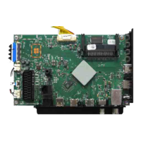
Component layout and connection points for the VTY190R-3 chassis.

Block Circuit Diagram

High-level functional diagram of the VTY190R-3 chassis components and their interconnections.

Special Functions

Service Hint

Remove the BMS Front Cabinet

Step-by-step guide for safely removing the front cabinet assembly.

Operating Hints

AT A GLANCE: Connections on the television set

Visual guide to all external connections on the TV set.

AT A GLANCE: Controls on the television set

Identification and function of the TV's physical control buttons.

CONVENIENCE FUNCTIONS

Updating software

Guide on how to update the TV's software for improved functionality.

Restoring the television to the default settings

Process to reset the TV to factory defaults, erasing all custom settings.

OPERATION USING EXTERNAL DEVICES

OVERVIEW

The remote control – Main functions

Explains the main buttons on the remote control for TV operation.

The remote control – All functions

Detailed explanation of all remote control functions for various modes like teletext and media playback.

Service and Special Functions

1. Basic Settings

Table detailing essential initial settings for various TV models in service mode.

Chassis Board – Block Circuit Diagram (VTY190R-3)

Chassis Board – Power Supply, USB, Keyboard (VTY190R-23)

Chassis Board – HDMI (VTY190R-23)

Chassis Board – SCART, VGA (VTY190R-23)

Chassis Board – Tuner / DVB-T2 (VTY190R-23)

Chassis Board – DVB-S (VTY190R-23)

Chassis Board – PCMCIA-Interface (VTY190R-23)

Chassis Board – Scaler (VTY190R-23)

Chassis Board – RAM (VTY190R-23)

Chassis Board – LVDS (VTY190R-23)

Chassis Board – Converter (VTY190R-23)

Chassis Board – Amplifier (VTY190R-23)

Related product manuals