EasyManua.ls Logo

Grundig KM 12 User Manual

Grundig KM 12
32 pages
To Next Page IconTo Next Page
Page #1 background imageLoading...
Page #1 background image
Service Manual
HiFi
BASS BOOST
S SKIP/SEARCH T
C
D
REMOTE SENSOR
DISC
12
3
TUNER
TAP
CD
aB;
9
VOLUME
DSC
a/
OPEN/CLOSE
DIGITAL SOUND CONTROL
3 - DISC CD CHANGER
HIFI STEREO MINI SYSTEM -
KM12
CD SYNCHRO RECORD
DECK A
RECORD/PLAYBACK
DECK B
PLAYBACK
FULL AUTOMATIC STOP
0 RECORD
Q
R
9//
;
Q
R
9//
;
B
B
ON/OFF
30 STATIONS
PRESET MEMORY
3
1
2
MEMORY
AUTO STORE
CD PROGRAM
MODE
SE
TIMER
CLOC
CLOCK
LIGHT
PRESET
PRESET
KM 12
Zusätzlich erforderliche
Unterlagen für den Komplettservice
Additionally required
Service Manuals for the Complete Service
Service
Manual
Service
Manual
Btx * 32700 #
Sachnummer
Part Number 72010-754.30
Änderungen vorbehalten
Subject to alteration
Printed in Germany
VK232 0697
KM 12
Sach-Nr./Part No.
72010-754.30
Sicherheit
Safety
Sach-Nr./Part No.
72010-800.00
Question and Answer IconNeed help?

Do you have a question about the Grundig KM 12 and is the answer not in the manual?

Grundig KM 12 Specifications

General IconGeneral
BrandGrundig
ModelKM 12
CategoryStereo System
LanguageEnglish

Summary

General Section

Test Equipment and Aids

Lists necessary tools and equipment for service.

Technical Data

Provides detailed specifications and parameters for the device.

Service Hints

Offers crucial advice for handling specific components like the laser unit.

Disassembly Instructions

Step-by-step guide for taking the unit apart.

Operating Instructions

Explains how to use the device's functions and features.

Adjustment Procedures

Tuner Alignment

Details the calibration process for the radio tuner section.

Cassette Section Adjustment

Outlines procedures for calibrating tape playback speed and azimuth.

CD Section Adjustment

Covers calibration steps for RF Gain and E-F Balance in the CD player.

Layouts and Diagrams

Block Diagrams

Shows the overall system architecture and signal flow.

Wiring Diagram

Illustrates how components and PCBs are interconnected electrically.

Circuit Diagrams

Provides detailed electrical schematics for various sections of the device.

PCB Layouts

Shows the physical arrangement and component placement on circuit boards.

IC Block Diagrams

Details the internal functions and pinouts of integrated circuits.

Spare Parts and Exploded Views

Exploded View - Main Unit

Visual breakdown of the entire unit with numbered parts.

Exploded View - CD Part

Detailed visual breakdown of the CD mechanism assembly.

Spare Parts List

Comprehensive list of all replaceable parts with part numbers.
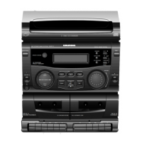
Related product manuals